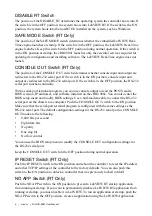
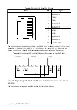
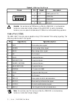
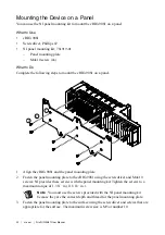

Table 2.
RS-485/422 Serial Port Pinout
Pinout
Pin
Signal
3
4
5
6
7
8
9
10
1
2
1
No Connect
2
TXD-
3
TXD+
4
No Connect
5
No Connect
6
RXD-
7
RXD+
8
No Connect
9
No Connect
10
Isolated GND
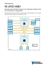
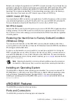
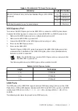
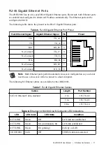
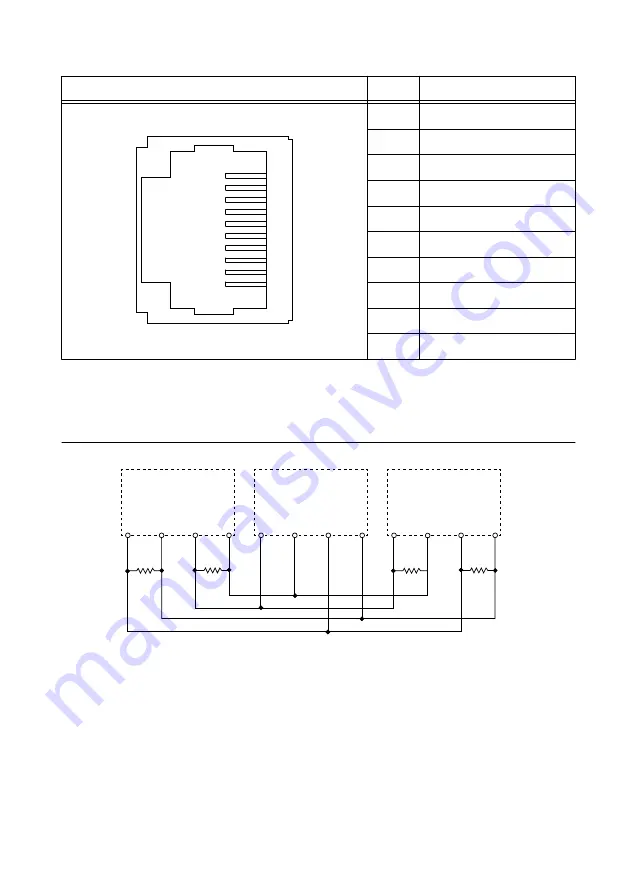
The following figure shows how to wire several NI FP-1001 banks in an RS-485/422 network
controlled by the cRIO-9081. Only two FP-1001 banks are shown, but the cRIO-9081 can
control up to 24 nodes. Install 120 Ω termination resistors at each end of the network.
Figure 2.
Wiring for an RS-485/422 Network Controlled by the cRIO-9081
RXD– RXD+ TXD– TXD+ RX–
RX+
TX–
TX+
RX–
RX+
TX–
TX+
cRIO-908x
FP-1001
FP-1001
120
Ω
120
Ω
120
Ω
120
Ω
COM 2 is designed to operate in four-wire (RS-422) mode. You can also use COM 2 in two-
wire mode.
The following accessories are available for the RS-485/422 serial port.
8
|
ni.com
|
NI cRIO-9081 User Manual