Chapter 2
Analog Input Timing/Control
DAQ-STC Technical Reference Manual
2-10
©
National Instruments Corporation
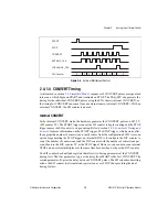
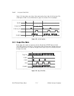
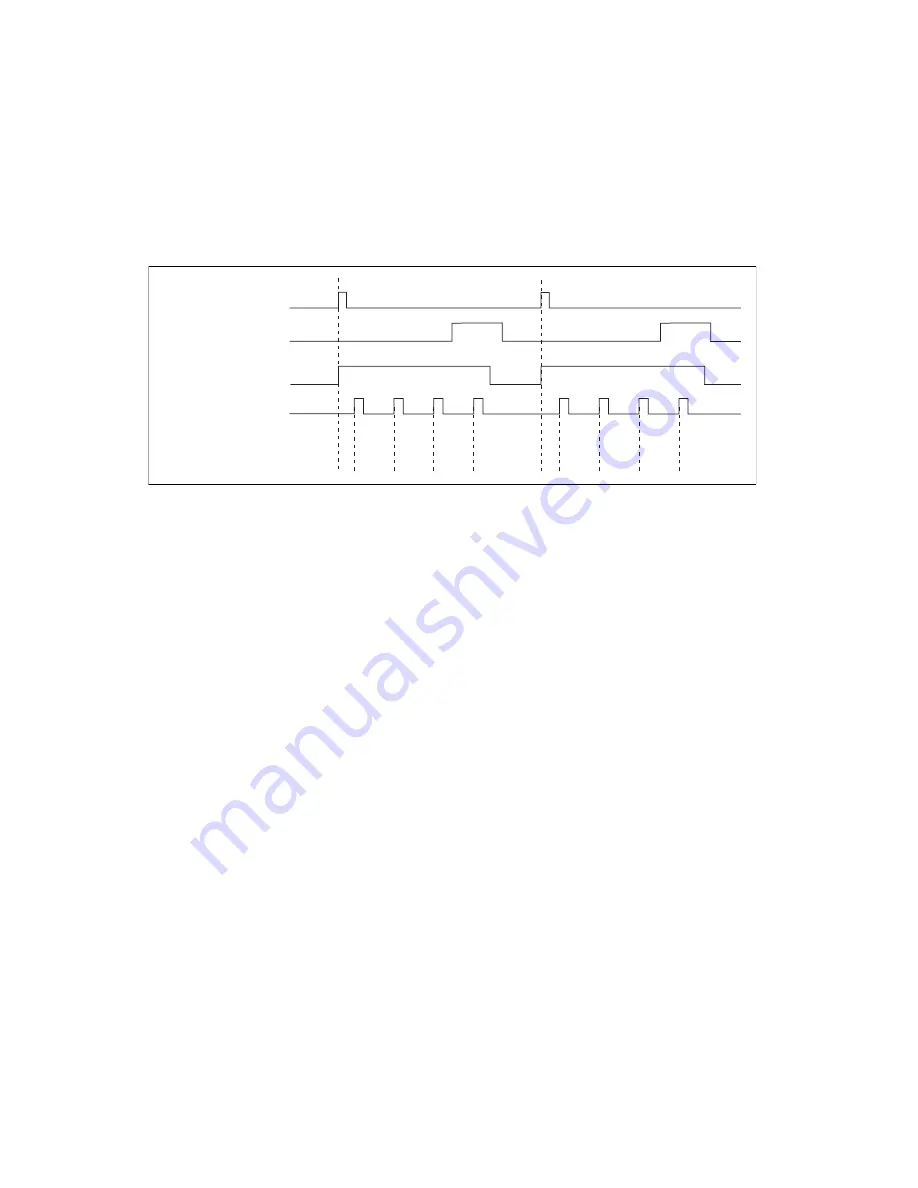
Figure 2-6 shows two scans with four internally timed CONVERT pulses each to indicate the
available timing parameters. The SCAN_IN_PROG output asserts on START and deasserts
at the completion of the scan.
Figure 2-6.
Internal CONVERT Timing
External CONVERT
In the external CONVERT mode, the externally generated CONVERT pulses enter the
DAQ-STC through one of the PFI<0..9> or RTSI_TRIGGER<0..6> inputs. In order to
preserve the concept of interval scanning with an external CONVERT, the STST_GATE
(Start/Stop Gate) is available. The START trigger enables the STST_GATE and the STOP
trigger disables the STST_GATE.
External CONVERT pulses that occur when the STST_GATE is enabled pass through the
DAQ-STC. External CONVERT pulses that occur when the STST_GATE is disabled are
blocked.
Timing for the external CONVERT can be arbitrarily complex depending on the behavior of
the signal you select as the external CONVERT source. Typically, though, you will select a
periodic signal, in which case the only timing parameter available is the delay between
CONVERT pulses. The delay from START to the first CONVERT depends on the
relationship between the START trigger and the external CONVERT and can vary.
Figure 2-7 shows two scans with four externally timed CONVERT pulses each and indicates
how the delay from START to the first CONVERT can vary. The SCAN_IN_PROG output
asserts on the recognition of START and deasserts on STOP.
STOP
SCAN_IN_PROG
CONVERT (SI2_TC)
Timing Parameter
START
A
B
B
B
A
B
B
B

