Index
DAQ-STC Technical Reference Manual
I-28
©
National Instruments Corporation
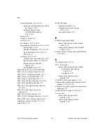
clock distribution, 10-2 to 10-3
master/slave distribution across RTSI
bus (figure), 10-2
timebases derived from
IN_TIMEBASE (table),
10-2 to 10-3
features, 10-1
frequency output, 10-3
overview, 10-1
pin interface, 10-9 to 10-10
programming information, 10-10 to 10-15
analog trigger, 10-12
bitfield descriptions, 10-12 to 10-15
clock distribution, 10-10 to 10-11
FOUT, 10-12
test mode, 10-6 to 10-9
checking input pin connectivity, 10-7
input pin pairs (table), 10-8 to 10-9
internal gate tree structure
(figure), 10-7
testing RESET pin, 10-8
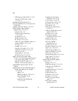
Motorola bus. See bus interface module.
MSC_Clock_Configure function, 10-11
MSC_FOUT_Configure function, 10-12
MSC_Generic_Control function, 7-12
MSC_Generic_Status function, 7-13
MSC_IRQ_Configure function, 8-3 to 8-4
MSC_IRQ_Personality function, 8-3
MSC_Pass_Through_Interrupt function,
8-4 to 8-5
MSC_Pass_Through_Second_Irq
function, 8-5
MSC_Write_Strobe function, 9-4
MSC_IO_Pin_Configure function, 5-5 to 5-6
MSC_RTSI_Pin_Configure function, 6-3
multiplexer control, external, 2-7 to 2-9
mute buffers, 3-15
MUXFEF signal
configuration FIFO, 2-8
configuration memory timing,
2-89 to 2-91
description (table), 2-22
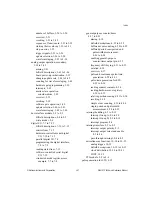
N
nominal signal pulsewidths
analog input timing/control module
(table), 2-133
analog output timing/control module
(table), 3-1124
number of scans, analog input programming,
2-32 to 2-33
O
OSC signal (table), 10-10
OUT_CLK signal
analog input timing/control module
basic analog input timing,
2-86 to 2-87
description, 2-85
analog output timing/control
module, 3-86
OUTBRD_OSC signal (table), 10-10
output control, analog output timing/control
module, 3-123 to 3-124
output pin for general-purpose counter/timer,
enabling, 4-35
OVER_DETECT signal, 2-86 to 2-87
overrun error
analog input timing/control
module, 2-132
analog output timing/control
module, 3-122


