background image

© 

National Instruments Corp.

9

FP-DI-330 and cFP-DI-330

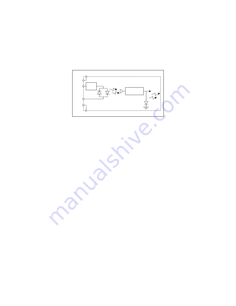
Figure 10 shows the input circuitry for a single channel.

Figure 10.  

[c]FP-DI-330 Input Circuit

Sensing DC Voltages

When an external device applies a positive or negative DC voltage 
with a magnitude of at least 4 V across the IN

a

 and IN

b

 terminals, 

the [c]FP-DI-330 registers an ON condition. The [c]FP-DI-330 
limits the current drawn by the input circuit to approximately 
1.5 mA for voltages up to 250 V.

When an external device applies a voltage with a magnitude of less 
than 1 V to the IN

a

 and IN

b

 terminals, the [c]FP-DI-330 registers 

an OFF condition. When the external device applies a voltage 
between –4 and –1 V or between 1 and 4 V, the [c]FP-DI-330 may 
or may not register an ON condition.

Ensure that the devices you connect to the [c]FP-DI-330 have 
OFF-state leakage currents lower than 350 

µ

A. Higher leakage 

currents can cause false ON readings.

The filter on the [c]FP-DI-330 inputs cause a delay of 
approximately 1.2 ms between the time a voltage changes from the 
ON state to the OFF state and the time the [c]FP-DI-330 recognizes 
the change. The delay for a transition from an OFF to an ON state 
is approximately 0.2 

µ

s.

Sensing AC Voltages

The [c]FP-DI-330 senses a wide range of AC signals. The 
minimum ON-state voltage for an AC signal depends on the 
frequency of the signal. When an external device applies a voltage 
between 1 V and the minimum ON-state voltage across the input 
terminals, the channel may or may not register an ON condition. 

IN

a

V

SUP

COM

IN

b

V

C

Status

Indicators

Optical

Isolation

[c]FP-DI-330

Current

Limiter

AC Smoothing

Filter

Summary of Contents for FieldPoint cFP-DI-330

Page 1: ... FP DI 330 is a FieldPoint digital input module with the following features Eight digital input channels Universal inputs that work with any voltage from 5 V TTL level up to 250 VDC VAC Compatibility with sourcing sinking or power sensing applications On Off LED indicators 250 Vrms CAT II continuous channel to ground isolation verified by 2 300 Vrms 1 minute dielectric withstand test 40 to 70 C op...

Page 2: ...Compact FieldPoint backplane cFP BP x which provides operating power to the module Installing the cFP DI 330 onto a powered backplane does not disrupt the operation of the bank To install the cFP DI 330 refer to Figure 2 and complete the following steps 1 Align the captive screws on the cFP DI 330 with the holes on the backplane The alignment keys on the cFP DI 330 prevent backward insertion 2 Pre...

Page 3: ...onnector block provides the same connections for the cFP DI 330 You can wire each channel to a switch a sourcing output device a sinking output device or a load Each channel has two input terminals INa and INb a supply terminal VSUP and a common terminal COM All eight COM terminals are internally connected to each other and to the C terminals All eight VSUP terminals are internally connected to ea...

Page 4: ...x connector blocks If you are using the cFP DI 330 in a hazardous voltage application you must use the cFP CB 1 connector block or a suitable hazardous voltage cable A hazardous voltage is a voltage greater than 42 4 Vpeak or 60 VDC Caution Ensure that hazardous voltage wiring is performed only by qualified personnel adhering to local electrical standards Caution Do not mix circuits with hazardous...

Page 5: ...ure 3 Connecting Devices to the c FP DI 330 Sinking Output Device NPN c FP DI 330 VSUP COM V C Input Circuitry INb Ch 1 INa Ch 1 Sourcing Output Device PNP VSUP COM Input Circuitry INb Ch 2 INa Ch 2 Sinking Output Device NPN VSUP COM Input Circuitry INb Ch 3 INa Ch 3 Sourcing Output Device PNP VSUP COM Input Circuitry INb Ch 4 INa Ch 4 Switch VSUP COM Input Circuitry INb Ch n INa Ch n 5 250 V Exte...

Page 6: ...g a Sourcing Output Device to the c FP DI 330 To connect a sourcing output device to the c FP DI 330 connect a power supply to the V and C terminals of the c FP DI 330 Connect the VSUP INa INb and COM terminals to the sourcing output device Figure 5 Wiring the c FP DI 330 to a Sourcing Output Device Switch c FP DI 330 VSUP COM V C Input Circuitry INb INa 5 250 V External Power Supply 2 A Max Sourc...

Page 7: ...ing Output Device to the c FP DI 330 To connect a sinking output device to the c FP DI 330 connect a power supply to the V and C terminals of the c FP DI 330 Connect the VSUP INa INb and COM terminals to the sinking output device Figure 7 Wiring the c FP DI 330 to a Sinking Output Device Sourcing Output Device PNP c FP DI 330 VSUP COM V C Input Circuitry INb INa Sinking Output Device NPN c FP DI 3...

Page 8: ...re 9 Wiring the c FP DI 330 to a Load Universal Input Circuit The c FP DI 330 has eight current limited universal input channels with bi directional optical isolators Each channel has two interchangeable signal inputs INa and INb When you apply a voltage across the INa and INb terminals signal current flows through the input circuitry and turns on the optical isolator registering as an ON conditio...

Page 9: ...0 may or may not register an ON condition Ensure that the devices you connect to the c FP DI 330 have OFF state leakage currents lower than 350 µA Higher leakage currents can cause false ON readings The filter on the c FP DI 330 inputs cause a delay of approximately 1 2 ms between the time a voltage changes from the ON state to the OFF state and the time the c FP DI 330 recognizes the change The d...

Page 10: ...30 it sends initial configuration information to the c FP DI 330 After the c FP DI 330 receives this initial information the green READY indicator lights and the module is in normal operating mode In addition to the green POWER and READY indicators each channel has a numbered green status indicator that lights when the channel is in the ON state Isolation and Safety Guidelines Caution Read the fol...

Page 11: ...nal supply voltages the V and C terminals with other devices including other FieldPoint devices unless those devices are isolated from human contact For Compact FieldPoint you must connect the protective earth PE ground terminal on the cFP BP x backplane to the system safety ground The backplane PE ground terminal has the following symbol stamped beside it Connect the backplane PE ground terminal ...

Page 12: ...he c FP DI 330 at or below Installation Category II Installation Category II is for measurements performed on circuits directly connected to the low voltage installation This category refers to local level distribution such as that provided by a standard wall outlet Specifications The following specifications are typical for the range 40 to 70 C unless otherwise noted Specifications are subject to...

Page 13: ...200 mW Isolation Voltage Channel to ground isolation Continuous 250 Vrms Installation Category II Dielectric withstand 2 300 Vrms 1 minute Channel to channel isolation None Environmental FieldPoint modules are intended for indoor use only For outdoor use they must be mounted inside a sealed enclosure Operating temperature 40 to 70 C Storage temperature 55 to 85 C Humidity 10 to 90 RH noncondensing...

Page 14: ...s designed to meet the requirements of the following standards of safety for electrical equipment for measurement control and laboratory use IEC 61010 1 EN 61010 1 UL 3121 1 UL 61010C 1 CAN CSA C22 2 No 1010 1 For UL hazardous location and other safety certifications refer to the product label or visit ni com hardref nsf search by model number or product line and click the appropriate link in the ...

Page 15: ...gulatory compliance information To obtain the DoC for this product visit ni com hardref nsf search by model number or product line and click the appropriate link in the Certification column Mechanical Dimensions Figure 12 shows the mechanical dimensions of the FP DI 330 installed on a terminal base If you are using the cFP DI 330 refer to your Compact FieldPoint controller user manual for the dime...

Page 16: ... help address your support needs For telephone support in the United States create your service request at ni com support and follow the calling instructions or dial 512 795 8248 For telephone support outside the United States contact your local branch office Australia 1800 300 800 Austria 43 0 662 45 79 90 0 Belgium 32 0 2 757 00 20 Brazil 55 11 3262 3599 Canada Calgary 403 274 9391 Canada Ottawa...

Reviews: