FP-DI-330 and cFP-DI-330
10
ni.com
The AC smoothing filter shown in Figure 10 ensures that the
channel remains ON if the signal frequency is higher than 50 Hz
and the signal voltage is higher than the minimum ON state. Refer
to the
section for more information about minimum
ON-state voltages and digital logic levels.
Status Indicators
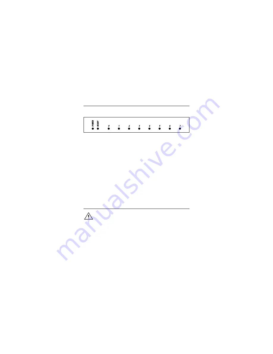
Figure 11 shows the status indicator LEDs on the [c]FP-DI-330.
Figure 11.
Status Indicators
The [c]FP-DI-330 has two green status LEDs,
POWER
and
READY
. After you insert the [c]FP-DI-330 into a terminal base
or backplane and apply power to the connected network module,
the green
POWER
indicator lights and the [c]FP-DI-330 informs
the network module of its presence. When the network module
recognizes the [c]FP-DI-330, it sends initial configuration
information to the [c]FP-DI-330. After the [c]FP-DI-330 receives
this initial information, the green
READY
indicator lights and the
module is in normal operating mode.
In addition to the green
POWER
and
READY
indicators, each
channel has a numbered green status indicator that lights when the
channel is in the ON state.
Isolation and Safety Guidelines
Caution
Read the following information before
attempting to connect the [c]FP-DI-330 to any circuits
that may contain hazardous voltages.
This section describes the isolation of the [c]FP-DI-330 and its
compliance with international safety standards. The field wiring
connections are isolated from the backplane and the inter-module
communication bus. The isolation barriers in the module provide
250 V
rms
Installation Category II continuous isolation, verified by
2,300 V
rms
, 1 minute dielectric withstand test. The [c]FP-DI-330
provides
double insulation
(compliant with IEC 61010-1) for


