Chapter 2
Configuration and Installation
© National Instruments Corporation
2-3
GPIB-110 User Manual
The GPIB-110 Front and Rear Panels
In the following discussions, the terms local and remote refer to certain states of the two
GPIB-110 Bus Extenders. When one extender is in a local state, meaning that the state in
question originated on its side, the other extender is in the corresponding remote state. The three
states in question are the System Controller, Active Controller, and Source Handshake.
The GPIB-110 Front Panel
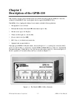
The GPIB-110 front panel is shown in Chapter 1, Figure 1-1. The front panel has nine Light
Emitting Diodes (LEDs). The PWR LED on the left side of the front panel lights up whenever
power is applied to the GPIB-110.
The Serial Communication LEDs are LINK and ERR (error). The GPIB-110 condenses the 16
IEEE 488 signals into data packets that are sent across the serial link and are converted back to
IEEE 488 signals by the remote GPIB-110. When lit, the LINK LED indicates that the remote
GPIB-110 is on and the extension is operating normally. The ERR LED flashes whenever a data
packet containing an error is received.
The System Controller, Active Controller, and Source Handshake each have two LEDs
indicating local (LOC) and remote (REM). If the System Controller LOC LED is lit, the
Interface Clear (IFC) or Remote Enable (REN) message has been detected on the local GPIB. If
the System Controller REM LED is lit, IFC or REN has been received from the remote unit. If
the Active Controller LOC LED is lit, the Attention (ATN) message has been detected on the
local GPIB. If the Active Controller REM LED is lit, ATN has been received from the remote
unit. If the Source Handshake LOC LED is lit, a Data Valid (DAV) message has been detected
on the local GPIB; that is, the Talker is on the local GPIB. If the REM LED lights up, DAV has
been received from the remote unit; that is, the Talker is on the remote side.


