Configuration and Installation
Chapter 2
GPIB-110 User Manual
2-4
© National Instruments Corporation
The GPIB-110 Rear Panel
The GPIB-110 rear panel is shown in Figure 2-2. The rear panel contains all the GPIB-110
connectors and switches.
Figure 2-2. Rear Panel
The rear panel shown is for the 776103-03 (776103-33) model, which supports both fiber optic
and coaxial cable.
For all models, the power switch is located on the upper right corner of the rear panel. The fuse
housing is located directly to the right of the power switch. The GPIB connector is located
directly below the power switch and is labeled GPIB. To the left of the GPIB connector (center
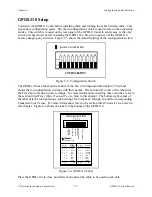
bottom of panel) is the configuration switch, which is labeled CONFIGURATION.
For the 776103-01 (776103-31) and 776103-03 (776103-33) models, an LED is located to the
left of the configuration switch. The LED labeled FO SIGNAL OK is lit when the signal quality
received over the fiber optic cable is good. To the left of the LED are the optical fiber
connectors labeled RCVR for receive and TRANS for transmitter.
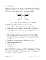
For the 776103-02 and 776103-03 models, the coaxial cable connector is located on the left-most
bottom corner of the rear panel. The connector is labeled COAX.

