background image

© National Instruments Corporation

A-1

GPIB-110 User Manual

Appendix A
Hardware Specifications


This appendix lists the specifications of the GPIB-110.

System Configuration

Distance per extension

Up to 2 km

Loading per extension

Up to 14 additional devices

Multiple extensions

Permitted in any combination of star or linear
pattern

GPIB driver output circuit and T1 timing 

No restrictions (automatic conversion to 0.5 

µ

sec

of source device

T1 delay on remote side is built-in)

Note: T1 is the data settling time (DIO valid to DAV) and varies according to the type of

drivers and the system configuration used.

Performance Characteristics

Speed

Up to 144 kbytes/sec (speed depends on type of

serial link and distance).  See Table A-1.

No limitation to device speeds when there are no
listeners on remote side of extension

Table A-1.  Performance Versus Distance

Performance

Cable

Cable Length

Measurement

Type

short

250 m

500 m

1000 m

1500 m

2000 m

Max Data Transfer
Rate (kbytes/sec)

Fiber Optic
Coaxial

144.0
144.0

108.0
108.0

85.0
33.0

56.0
17.9

44.0

1.6

36.0

0.4

Max SRQ Prop.
Delay (

µ

sec)

Fiber Optic
Coaxial

11.0
11.6

14.0
14.8

18.0
35.4

27.0
67.0

35.0

378.0

44.0

1450.0

Max Parallel Poll
Response Delay (

µ

sec)

Fiber Optic
Coaxial

17.0
23.9

21.0
30.8

26.0
53.2

38.0
98.0

48.0

606.0

58.0

2340.0

Summary of Contents for GPIB-110

Page 1: ...Copyright 1986 1994 National Instruments Corporation All Rights Reserved GPIB 110 User Manual August 1994 Edition Part Number 320052 01...

Page 2: ...ices Australia 03 879 9422 Austria 0662 435986 Belgium 02 757 00 20 Canada Ontario 519 622 9310 Canada Qu bec 514 694 8521 Denmark 45 76 26 00 Finland 90 527 2321 France 1 48 14 24 24 Germany 089 741...

Page 3: ...against National Instruments must be brought within one year after the cause of action accrues National Instruments shall not be liable for any delay in performance due to causes beyond its reasonable...

Page 4: ...ference from the equipment to radio reception in commercial areas Operation of this equipment in a residential area is likely to cause harmful interference in which case the user will be required to c...

Page 5: ...3 The GPIB 110 Rear Panel 2 4 GPIB 110 Setup 2 5 Cable Selection 2 6 Coaxial Cable Setup 2 6 Fiber Optic Cable Setup 2 7 Master Switch Setting 2 7 Fiber Optic Transmit Power 2 7 Transmit Clock 2 8 Ex...

Page 6: ...ock 3 8 Appendix A Hardware Specifications A 1 System Configuration A 1 Performance Characteristics A 1 Operating Characteristics A 2 Electrical Characteristics A 2 Environmental Characteristics A 3 P...

Page 7: ...3 Typical GPIB 110 Extension System Logical Configuration 1 2 Figure 2 1 Isolation Selection 2 2 Figure 2 2 Rear Panel 2 4 Figure 2 3 Configuration Switch 2 5 Figure 2 4 GPIB 110 Label 2 5 Figure 2 5...

Page 8: ...ndix A Hardware Specifications lists the specifications of the GPIB 110 Appendix B Multiline Interface Messages lists the multiline interface messages and describes the mnemonics and messages that cor...

Page 9: ...erms are listed in the Glossary Related Documentation The following manual contains information that may be helpful as you read this manual ANSI IEEE Standard 488 1 1987 IEEE Standard Digital Interfac...

Page 10: ...up to 2 km Transfer rates up to 144 kbytes s Choice of fiber optic or coaxial cable Passes control over the GPIB FCC Class A verified noise emission Optional rack mount hardware The high speed GPIB 11...

Page 11: ...with an extended system When conducting a parallel poll with an extended system minor modifications are necessary These are explained in the section titled Parallel Poll Response PPR Modes in Chapter...

Page 12: ...nd the loading limit to 30 devices including the extenders You can connect these point to point extender systems in series for longer distances or in star patterns for additional loading What Your Kit...

Page 13: ...ng your GPIB 110 1 Verify that the pieces contained in the package you received match the kit parts list given earlier in this chapter 2 Before you operate the GPIB 110 inspect the shipping container...

Page 14: ...GPIB 110 When connected to a power source this cable connects the equipment chassis to the power ground The GPIB 110 is shipped from the factory with the logic ground of the digital circuitry connecte...

Page 15: ...R1 C60 C9 R6 C3 U4 U15 U16 C6 C7 C10 C8 U20 J4 MIT J3 RCV C61 R9 D9 U51 U52 U17 U18 D1 D2 D3 C21 U34 U35 U36 U37 C30 U53 U54U55 U56 U57 R1 U73 U74 U75 U76 U77 U78 S1 J5 C42 U94 U95 U96 U97 U98 U99 C44...

Page 16: ...hat are sent across the serial link and are converted back to IEEE 488 signals by the remote GPIB 110 When lit the LINK LED indicates that the remote GPIB 110 is on and the extension is operating norm...

Page 17: ...of the power switch The GPIB connector is located directly below the power switch and is labeled GPIB To the left of the GPIB connector center bottom of panel is the configuration switch which is labe...

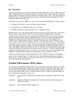
Page 18: ...bottom left corner of the label lists the Fiber Optic Transmit power settings For more information on setting these switches refer to the section titled Fiber Optic Transmit Power later in this chapt...

Page 19: ...B 110 3 Remove the cover from the GPIB 110 by first removing the two screws located on each side of the housing Lift off the cover 4 The Internal Cable Selection Jumper shown in Figure 2 5 is located...

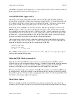
Page 20: ...110 to the OFF position The GPIB 110 with the master switch set in the OFF position is master Note The master switch settings are reversed from the markings that appear on the switch To set your GPIB...

Page 21: ...smit Clock Values Versus Cable Length Cable Type Cable Length Transmit Clock Configuration Switch Setting 10 9 8 Coaxial 0 m to 240 m 10 MHz 1 1 1 Cable 240 m to 425 m 5 MHz 1 1 0 425 m to 730 m 2 MHz...

Page 22: ...ontroller RAC state The ATN signal is switched to flow from the local to the remote side and the Service Request SRQ is switched to flow in the opposite direction Finally one unit detects the Data Val...

Page 23: ...sponse The software driver library of most Controllers contains an easy to use parallel poll function For example if the function is called PPOLL and the control program is written in BASIC the sequen...

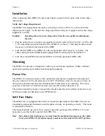
Page 24: ...ounting The GPIB 110 enclosure is designed for table top or rack mount operation Single and dual unit rack mount kits are available from National Instruments Power On The GPIB 110 extension system is...

Page 25: ...ith the fiber optic cable you must connect a single fiber optic cable in a loop from the transmit output to the receive input of the GPIB 110 You can use the opposite ends of the extension cable or pu...

Page 26: ...the GPIB lines of the Master Controller are terminated to represent six device loads HP has two types of preloading Class A in which all 16 GPIB lines are loaded and Class B in which all except Not Re...

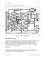
Page 27: ...s the signals monitored into the X for transmit signals that are sent to the serial communication circuitry The serial communication circuitry samples the X signal lines and serializes the information...

Page 28: ...Establishment F O Transmit Power Coax Transmitter and Receiver Receive Data Communication Circuitry Packet Reception Packet Reception and Decoding Timing Figure 3 1 GPIB 110 Block Diagram Extension Ci...

Page 29: ...is not received true Active Controller Detection The GPIB 110 monitors the location of the Active Controller with the Active Controller detection circuitry The location of the Active controller is det...

Page 30: ...When R DAV is received from the remote unit the signal is delayed 2 s and the RS state becomes true Once the RS state is true DAV is driven onto the local GPIB Subsequently whenever R DAV true is rece...

Page 31: ...RPP true is received and unlatched parallel poll response mode is selected the GPIB data lines are driven with the data from the data packet received from the remote unit If DAV is not true during a P...

Page 32: ...cket is not received the GPIB 110 times out and retransmits the packet This process continues until a packet is received When you power on the non master GPIB 110 waits to receive a packet from the ma...

Page 33: ...ith the cyclical redundancy check code appended to the packet If an error is detected the packet is discarded Otherwise the packet information is latched and sent to the extension circuitry The GPIB 1...

Page 34: ...and the GPIB 110 shuts down the GPIB drivers The unit then waits for link establishment Refer to the section Link Establishment Protocol earlier in this chapter System Timing and Transmission Clock S...

Page 35: ...ording to the type of drivers and the system configuration used Performance Characteristics Speed Up to 144 kbytes sec speed depends on type of serial link and distance See Table A 1 No limitation to...

Page 36: ...ontroller E2 Tri state GPIB drivers Operating Characteristics Architecture Synchronous clocked design point to point not multidrop transmission Operating modes Immediate extension or IFC wait extensio...

Page 37: ...Operating temperature 0 to 45 C Humidity 5 to 95 non condensing conditions FCC Class A verified Physical Characteristics Case style CS2 Size 3 5 in by 8 5 in by 13 in 89 mm by 216 mm by 330 mm Case m...

Page 38: ...the interface functions These functions include initializing the bus addressing and unaddressing devices and setting device modes for local or remote programming The multiline interface messages are...

Page 39: ...0E 016 14 SO 2E 056 46 MLA14 0F 017 15 SI 2F 057 47 MLA15 10 020 16 DLE 30 060 48 0 MLA16 11 021 17 DC1 LLO 31 061 49 1 MLA17 12 022 18 DC2 32 062 50 2 MLA18 13 023 19 DC3 33 063 51 3 MLA19 14 024 20...

Page 40: ...5 109 m MSA13 PPE 4E 116 78 N MTA14 6E 156 110 n MSA14 PPE 4F 117 79 O MTA15 6F 157 111 o MSA15 PPE 50 120 80 P MTA16 70 160 112 p MSA16 PPD 51 121 81 Q MTA17 71 161 113 q MSA17 PPD 52 122 82 R MTA18...

Page 41: ...ear C sre send remote enable C tca take control asynchronously C tcs take control synchronously AH C ton talk only T TE Remote Messages Received Mnemonic Message Interface Function s ATN attention SH...

Page 42: ...nlisten L LE ATN attention C DAB data byte DAC data accepted AH DAV data valid SH DCL device clear via C END end via T GET group execute trigger via C GTL go to local via C IDY identify C IFC interfac...

Page 43: ...0 User Manual B 6 National Instruments Corporation Interface Message Reference List Continued Remote Messages Sent Continued Mnemonic Message Interface Function s STB status byte via T TE TCT take con...

Page 44: ...Device dependent messages often called data or data messages contain device specific information such as programming instructions measurement results machine status and data files Interface messages m...

Page 45: ...only be a Talker called a Talk only device and there may be one or more Listen only devices A Controller is necessary when the active or addressed Talker or Listener must be changed The Controller fu...

Page 46: ...5 6 7 8 9 10 11 12 13 14 15 16 17 18 19 20 21 22 23 24 Figure C 1 GPIB Cable Connector Data Lines The eight data lines DIO1 through DIO8 carry both data and command messages All commands and most data...

Page 47: ...hich NRFD and NDAC are used by the receiving device is called the Acceptor Handshake Likewise the sending device uses DAV in the Source Handshake Interface Management Lines Five lines are used to mana...

Page 48: ...connected with a cable assembly consisting of a shielded 24 conductor cable with both a plug and receptacle at each end This design allows devices to be connected in either a linear or a star configu...

Page 49: ...The standard connector is the Amphenol or Cinch Series 57 Microribbon or Amp Champ type An adapter cable using non standard cable and or connector is used for special interconnect applications The GP...

Page 50: ...s The GPIB 110 is a serial extender that uses either low cost coaxial cable or high performance electrically isolated fiber optic cable as its transmission medium The GPIB 110 samples GPIB signals on...

Page 51: ...le Monday through Friday from 8 00 a m to 6 00 p m central time In other countries contact the nearest branch office You may fax questions to us at any time Corporate Headquarters 512 795 8248 Technic...

Page 52: ...ficiently If you are using any National Instruments hardware or software products related to this problem include the configuration forms from their user manuals Include additional pages if necessary...

Page 53: ...form as a reference for your current configuration National Instruments Products GPIB 110 Revision Remote GPIB 110 Revision National Instruments GPIB Interface National Instruments Software Fiber Opt...

Page 54: ...art Number 320052 01 Please comment on the completeness clarity and organization of the manual If you find errors in the manual please record the page numbers and describe the errors Thank you for you...

Page 55: ...ASCII American Standard Code for Information Exchange BNC refers to coaxial cable connector C Celsius CIC Controller In Charge CPU central processing unit dB decibels DC direct current EOI End or Iden...

Page 56: ...ters MB megabytes of memory Mbytes 1 000 000 bytes NA numerical aperture PPR Parallel Poll Response PVC Polyvinylchloride RAC Remote Active Controller REM Remote LED RS Remote Source state RSC Remote...

Page 57: ...clock 2 8 configuration switch default settings 2 5 illustration of 2 5 location of 2 4 possible configurations for 2 5 connectors and switches See also jumpers COAX connector 2 4 coaxial cable setup...

Page 58: ...not ready for data C 4 Hewlett Packard controllers 2 13 history of the GPIB C 1 I IFC line interface clear C 4 IFC Wait Mode 2 9 Immediate Extension Mode 2 8 installation See also configuration connec...

Page 59: ...tenders and expanders C 6 to C 7 System Controller and Active Controller C 2 Talkers Listeners and Controllers C 1 to C 2 types of messages C 1 P packets packet format 3 7 Receive Packet state 3 7 Tra...

Page 60: ...ation of 3 5 SRQ line service request C 4 switches See connectors and switches system configuration specifications A 1 System Controller Controller in Charge C 2 LEDs for 2 3 theory of operation 3 3 s...

Reviews: