© National Instruments Corporation
Index- 1
GPIB-110 User Manual
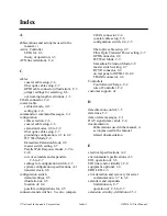
Index
A
abbreviations and acronyms used in the
manual, vi
Active Controller
LEDs for, 2-3
theory of operation, 3-3
ATN line (attention), C-4
C
cables
coaxial cable setup, 2-6
fiber optic cable setup, 2-7
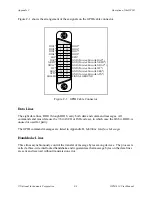
GPIB cable connector (illustration), C-3
jumper settings for selecting, 2-6
overcoming length restrictions, 1-3
COAX connector, 2-4
coaxial cable
self-test mode, 2-13
setting up, 2-6
commands or command messages, C-1
configuration
cable selection, 2-6
coaxial cable setup, 2-6
extension modes, 2-8 to 2-9
fiber optic cable setup, 2-7
grounding configuration, 2-1 to 2-2
IFC Wait Mode, 2-9
Immediate Extension Mode, 2-8
master switch setting, 2-7
Parallel Poll Response modes, 2-9 to
2-10
role of extenders and expanders,
C-6 to C-7
settings for configuration switch, 2-5
system configuration specifications, A-1
transmit clock, 2-8
configuration switch
default settings, 2-5
illustration of, 2-5
location of, 2-4
possible configurations for, 2-5
connectors and switches. See also jumpers.
COAX connector, 2-4
coaxial cable setup, 2-6
configuration switch, 2-4, 2-5
fiber optic cable setup, 2-7
Fiber Optic Transmit Power setting, 2-7
GPIB connector, 2-4
IFC Wait Mode, 2-9
Immediate Extension Mode, 2-8
master switch setting, 2-7
RCVR connector, 2-4
on rear panel of GPIB-110, 2-4
TRANS connector, 2-4
Controllers
Controller-in-Charge, C-2
role of Controller, C-2
customer support, vii
D
data direction control, 3-5
data lines, C-3
data or data messages, C-1
DAV signal (data valid), C-4
documentation
abbreviations used in the manual, vi
acronyms used in the manual
related documentation
E
electrical specifications, A-2
environmental specifications, A-3
EOI, operation of, 3-5
EOI line (end or identify), C-4
equipment, optional, 1-4
ERR LED, 2-3
error detection and recovery for serial
communication, 3-7 to 3-8
extenders and expanders
limitations on, C-7
operation of, C-6 to C-7
extension circuitry, definition of, 3-1


