Chapter 3
Installation and Configuration in S Mode
© National Instruments Corp.
3-3
GPIB-232CT User Manual
Set Configuration Switches
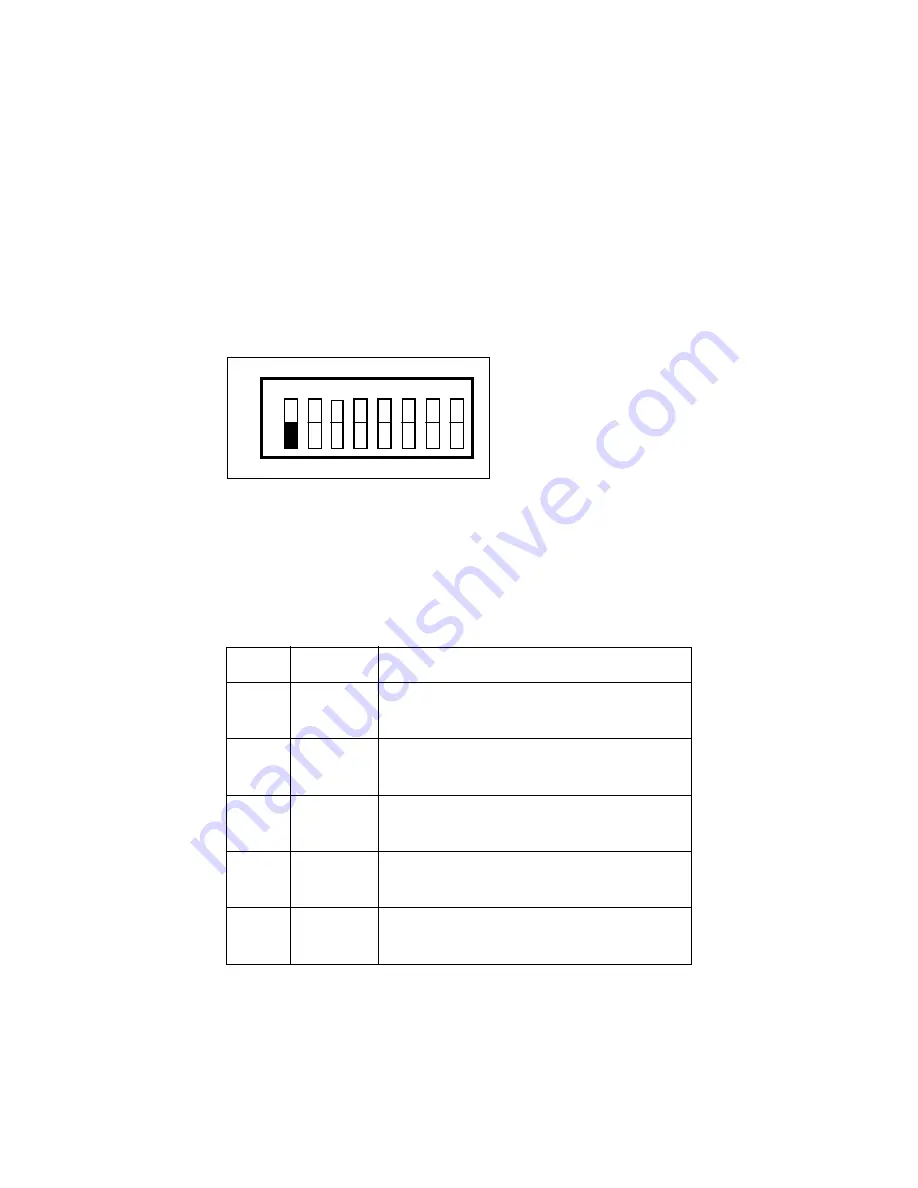
The DIP switch at location U22 on the printed wire board is used to
configure the serial port parameters of the GPIB-232CT while in S mode.
The DIP switch, shown in Figure 3-1, has eight configuration switches.
1
2
3
4
5
6
7
8
O
F
F
U22
O
N
ON indicates that the
switch is pressed on the
"ON" side.
OFF indicates that the
switch is pressed on the
"OFF" side.
Figure 3-1. S Mode Switch Settings
Tables 3-1 and 3-2 show the possible configurations of the eight switches
and what the configurations indicate.
Table 3-1. Configuration Parameters for Switches 1 through 5
!
Switch
Position
Indication
!
!
1
OFF
Configures the GPIB-232CT to operate in S mode.
!
ON
Configures the GPIB-232CT to operate in G mode.
!
!
2
OFF
7
bits/character.
!
ON
8
bits/character.
!
!
3
OFF
1 stop bit/character.
!
ON
2 stop bits/character.
!
!
4
OFF
Parity generation/checking disabled.
!
ON
Parity generation/checking enabled.
!
!
5
OFF
Odd
parity.
!
ON
Even
parity.
!


