Installation and Configuration of the GPIB-SCSI-A
Chapter 2
GPIB-SCSI-A User Manual
2-10
© National Instruments Corp.
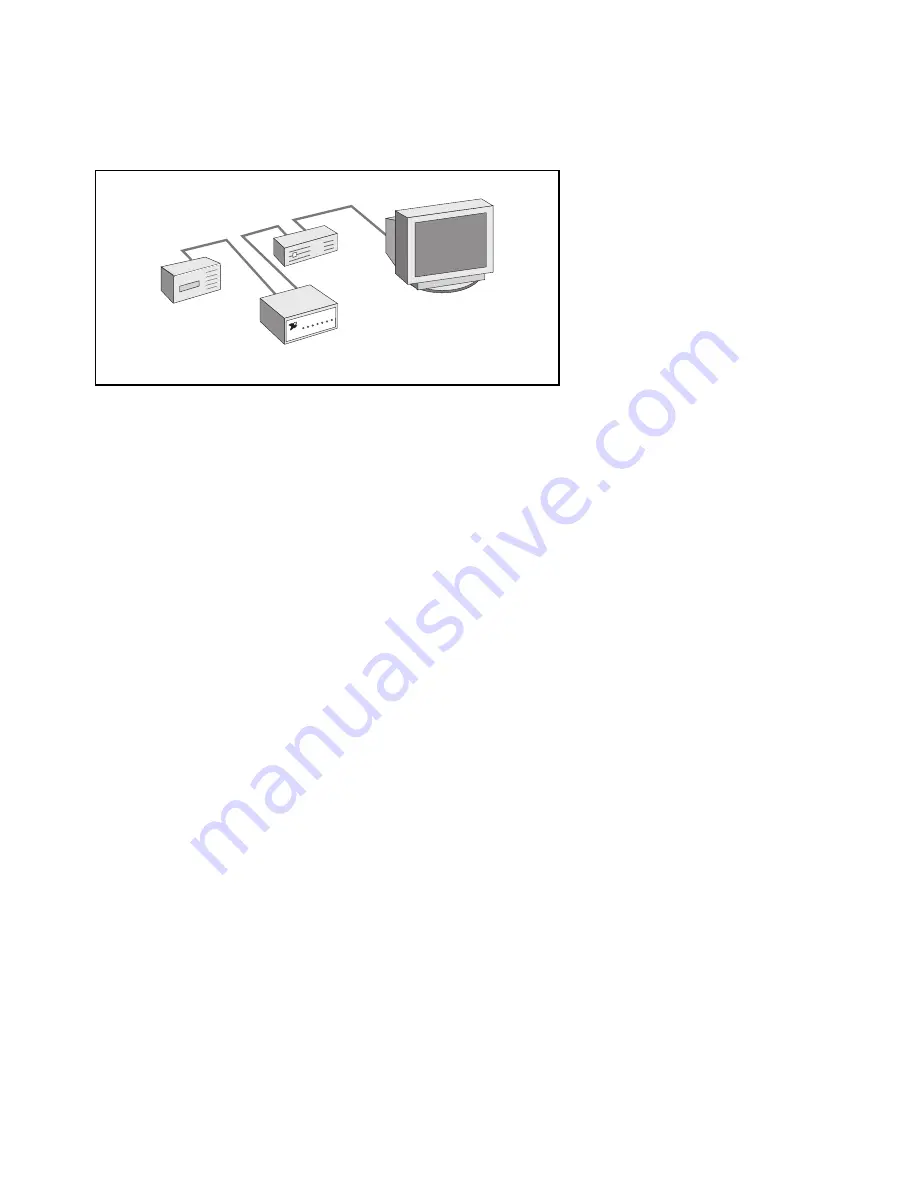
Figure 2-5 shows a system in which the GPIB-SCSI-A is not at the end of
the system.
SCSI host
GPIB-SCSI-A
SCSI tape
drive
SCSI disk
drive
Figure 2-5. GPIB-SCSI-A Not Physically Located at End of SCSI Bus
If this is similar to your application, ensure that all devices between the two
ends (for example, the two ends being the SCSI host and the SCSI tape
drive as shown in Figure 2-5) do not have terminating resistors installed.
Also remove the terminating resistor pack from the SCSI port on the rear
panel of the GPIB-SCSI-A.
Proper termination is absolutely essential to the devices connected on a
SCSI bus. Read the documentation for each device to find out what kind of
termination it provides.
Step 3. Connect the Cables
Caution:
Never connect or disconnect SCSI cables when any device
(computer, tape drive, GPIB-SCSI-A, and so on) is powered on.
Doing so can cause fuses to blow inside the GPIB-SCSI-A and
inside other SCSI devices which supply termination power
(TERMPWR) to the SCSI bus.


