Chapter 6
PCB Calculators
©
National Instruments Corporation
6-13
3.
In the
Input Data
area, edit the following fields as desired:
•
Input Length Unit
—Select mils or millimeters.
•
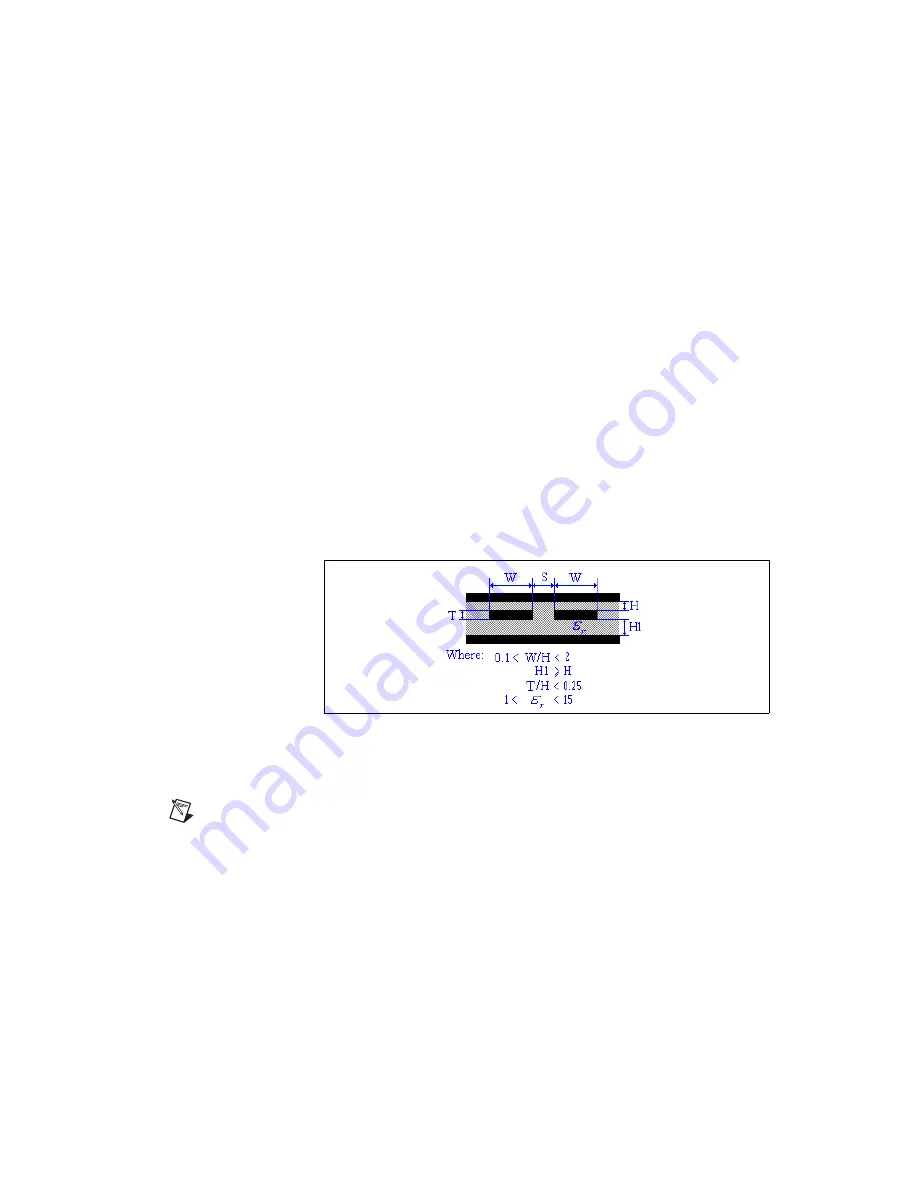
Dielectric Height (H1)
—Refer to the figure below.
•
Dielectric Height (H)
—Refer to the figure below.
•
Trace Thickness (T)
—Refer to the figure below.
•
Trace Width (W)
—Refer to the figure below.
•
Trace Spacing (S)
—Refer to the figure below.
•
Relative Permittivity (epsilon r)
—Refer to the figure below.
Or
If you wish to define the Characteristic Impedance (Zo) yourself, click
User Defined Zo
and edit the following fields as desired:
•
Input Length Unit
—Select mils or millimeters.
•
Dielectric Thickness (H)
—Refer to the figure below.
•
Trace Spacing (S)
—Refer to the figure below.
•
Characteristic Impedance (Zo)
—Refer to the figure below.
4.
Click
Calculate
. Results of the calculation appear in the
Calculation
Results
area. They also appear in the
Results
tab of the
Spreadsheet
View
.
Note
If you chose
User Defined Zo
in the previous step, the
Per Length Unit
and the
Differential Impedance
are the only values that appear in the
Calculation Results
area
of the
PCB Differential Impedance Calculator
dialog and the
Results
tab when you click
Calculate
.
5.
Click
Close
to close the
PCB Differential Impedance Calculator
.


