Chapter 3
Setting Up a Design
3-8
ni.com
4.
If you chose
Single Sided
or
Double Sided
, or upon clicking
Next
after defining the lamination settings for a multi-layer board:
•
Define the default
Units
of measurement for the design.
•
Define the board
Reference Point
. This can be changed later.
Refer to the
Setting the Board’s Reference Point
section for more
information.
•
Define the
Board Shape and Size
.
•
Set the default
Clearance
for the board—This is the distance from
the edge of the board that is to be kept free of any other elements.
Trying to run a trace through a clearance, or trying to place a part
so that a pad is put within a clearance, for example, results in a
design rule error.
5.
Click
Finish
. The board outline is placed on your design.
Setting the Board’s Reference Point
The reference point of the board is important for relating physical
dimensions to PCB layouts, since all measurements are shown relative to
this origin point. If you used the
Board Wizard
, this reference may already
have been set. Refer to the
section for more
information.
Complete the following steps to set a reference point:
1.
Choose
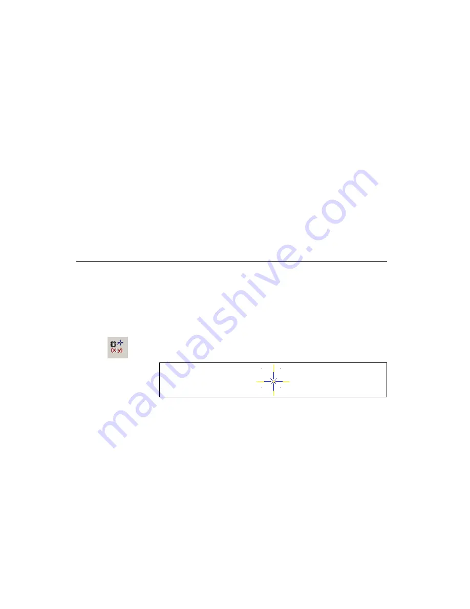
Design»Set Reference Point
. The cursor changes as shown in
the figure below.
2.
Click to place the reference point. In the example below, the reference
point has been placed at the lower left corner of the board outline.


