background image

Table 2. STATUS LED Indications

LED

LED

Color

LED State

Indication


STATUS

Yellow

OFF

The IC-3120 initialized successfully and is ready for
use.

2 blinks

(RT only) There is no software installed, which is the
out-of-box state, or the IC-3120 has detected an error
in its software. The device has automatically started
up into safe mode. This usually occurs when an
attempt to upgrade the software is interrupted or if
system files are deleted from the IC-3120. Reinstall
software on the IC-3120.

3 blinks

(RT only) The IC-3120 has booted into safe mode.
Refer to the 

Safe Mode

 section for information about

the safe mode state.

4 blinks

(RT only) The IC-3120 has experienced two
consecutive software exceptions. The IC-3120
automatically restarts after an exception. After the
second exception, the IC-3120 remains in the
exception state, alerting you to resolve the problem.
Reinstall software on the IC-3120 or contact NI for
assistance. Refer to the 

IC-3120 Getting Started

Guide

 for information about installing software on the

IC-3120.

Continuous

blinking

(RT only) The IC-3120 has not booted into NI Linux
Real-Time. The controller either booted into an
unsupported operating system, was interrupted during
the boot process, or detected an unrecoverable
software error.

Solid

(RT only) The IC-3120 is booting up.

(Windows only) An internal drive is being accessed.

PWR/FAULT LED Is Not Lit When the IC-3120 is
Powered On

If the system power supply is properly connected (polarity is not reversed) to the IC-3120, but
the PWR/FAULT LED does not light up, check that the power supply is within the
specifications listed in the 

IC-3120 Specifications

. Using a power supply that is not within

these specifications might result in an unresponsive or unstable system and could damage the
device.

12

  | 

ni.com

  | 

IC-3120 Getting Started Guide

Summary of Contents for IC-3120

Page 1: ...9 Troubleshooting 10 Where to Go Next 13 Worldwide Support and Services 13 Safety Information Caution The following paragraphs contain important safety information you must follow when installing and...

Page 2: ...efore returning it to service You must insulate signal connections for the maximum voltage for which the device is rated Do not exceed the maximum ratings for the device Remove power from signal lines...

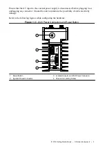
Page 3: ...ic electricity damage Refer to the following figures while configuring the hardware Figure 1 IC 3120 Power Connectors and Reset Button SYSTEM PoE 48 V ISO C ISO C PoE V PoE V ISO 5 24 V 12 24 V C V 2...

Page 4: ...ecommends the following power supply for the IC 3120 Power Supply Part Number NI PS 15 Industrial Power Supply 781093 01 Complete the following steps to supply power to the IC 3120 1 Verify the power...

Page 5: ...to 0 4 N m 3 5 lb in of torque 7 Turn on the external power source Connecting the Isolated Outputs Power Supply and PoE Power Supply NI recommends the following power supplies for the IC 3120 Power S...

Page 6: ...N m 1 8 to 2 2 lb in of torque 5 Connect the negative lead of the isolated outputs power source to the C2 terminal of the power connector plug and tighten the terminal screw to 0 2 to 0 25 N m 1 8 to...

Page 7: ...ment computer is powered on and connected to the network 2 Connect one end of an Ethernet cable to the network port on the device 3 Connect the free end of the cable to an Ethernet switch or other net...

Page 8: ...k Finish 7 Install custom software You do not need to install custom software if you installed a recommended software set a Expand the IC 3120 under Remote Systems b Click the Software item below the...

Page 9: ...ution NI cannot recover lost system passwords If you forget the password you must contact NI and reformat the controller Configuring the IC 3120 for Windows The Windows version of the IC 3120 ships pr...

Page 10: ...gured on another network and then moved to the current network Reconfigure the IC 3120 for the current network Note Connect a monitor and keyboard to the IC 3120 and press Enter to view the current co...

Page 11: ...ed as nati vi server NATI VI Server Used by Vision Builder AI to configure a remote target If your firewall is controlled remotely or you are unsure about configuring the firewall contact your network...

Page 12: ...the exception state alerting you to resolve the problem Reinstall software on the IC 3120 or contact NI for assistance Refer to the IC 3120 Getting Started Guide for information about installing soft...
Page 13: ...Factory Installation Services repairs extended warranty and other services Visit ni com register to register your NI product Product registration facilitates technical support and ensures that you rec...

Page 14: ...party legal notices in the readme file for your NI product Refer to the Export Compliance Information at ni com legal export compliance for the NI global trade compliance policy and how to obtain rel...

Reviews: