Chapter 2
Configuration and Installation
©
National Instruments Corporation
2-5
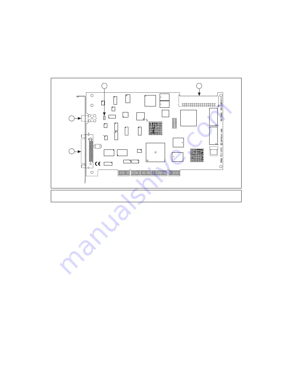
Figure 2-2 shows the locations of user-configurable jumpers and switches
as well as factory-default settings on the PCI-1409.
.
Figure 2-2.
PCI-1409 Parts Locator Diagram
1
68-pin VHDCI
Connector
2
BNC Connector
3
W1
4
RTSI Bus Connector
4
3
1
2


