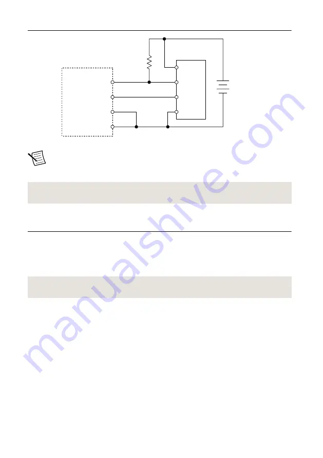
Figure 10.
Wiring a Lighting Controller Using an Isolated Output as Trigger
2 k
Ω
0.5 W
24 VDC
Supply
ICS 3 Lighting
Device
ISC-178x
Iso Out
Trigger
+
–
Analog Out
Analog
C
C
Out
+
–
Note
A different pull-up resistor may be used, as long as the isolated output sink
current specification is not exceeded and the resistor is appropriately rated for the
expected power dissipation.
Related Information
on page 16
Wiring the Isolated Inputs
The isolated inputs can be configured as current sinking or current sourcing. The configuration
depends on whether the common input signal is tied to ground (sinking input) or +V (sourcing
input). The isolated inputs cannot be configured individually. The isolated inputs must all be
sinking or must all be sourcing.
Related Information
Wiring an Isolated Input to a Sinking Output
The following figure shows how to wire the isolated inputs with a sourcing configuration to a
sinking output. The isolated inputs on the ISC-178x have a built-in current-limiting circuit.
The isolated inputs do not require a current-limiting resistor. Refer to the specifications of the
connected output device to determine if a resistor is needed to limit the output current.
ISC-178x User Manual
|
© National Instruments
|
13
Summary of Contents for ISC-1783
Page 1: ...ISC 1783...


