Chapter 3
Gabor Transform-Based Order Tracking
LabVIEW Order Analysis Toolset User Manual
3-8
ni.com
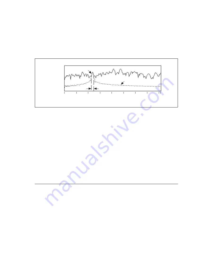
time-variant filters. Figure 3-6 shows an original signal and the spectrum of
the reconstructed signal.
Figure 3-6.
Spectrum of Reconstructed Signal
In Figure 3-6, one row is selected from the joint time-frequency coefficient
array. The selected row is nothing more than a windowed FFT power
spectrum in the time interval. The original Gabor coefficients comprise the
solid line in Figure 3-6. When performing a mask operation, coefficients
outside the expected passband are set to zero.
After reconstruction, the spectrum of the reconstructed signal is formed.
In Figure 3-6, the dashed line represents the spectrum of the reconstructed
signal. Within the passband, the reconstructed signal keeps the same
magnitude as the original signal. While outside the passband, the
magnitude of the reconstructed signal is no longer zero. Instead,
the magnitude does have some certain value. However, the value of
the magnitude quickly decreases as the frequency leaves the passband.
Displaying Spectral Maps
Before extracting order components from the joint time-frequency domain,
you might want to identify the order components in which you are most
interested, such as which order is the most significant or which order
contributes the most at a certain rotational speed. However, by using order
extraction and reconstruction, you might have to process a large number of
order components before you can obtain this information.
The LabVIEW Order Analysis Toolset provides several methods of
obtaining a 2D spectral map over the whole signal in the frequency-time,
frequency-rpm, and order-rpm domains. Figure 3-7 shows the three types
of spectral maps for a vibration signal.
Expected Pass Band
–49.1–
–100.0–
–150.0–
–179.0–
250
300
350
100
0
50
150
200
408
Frequency (Hz)
Original Signal
Reconstructed Order
dB


