Chapter 3
Hardware Overview
Fiber-Optic MXI-Express x4 for PXI Express User Manual
3-2
ni.com
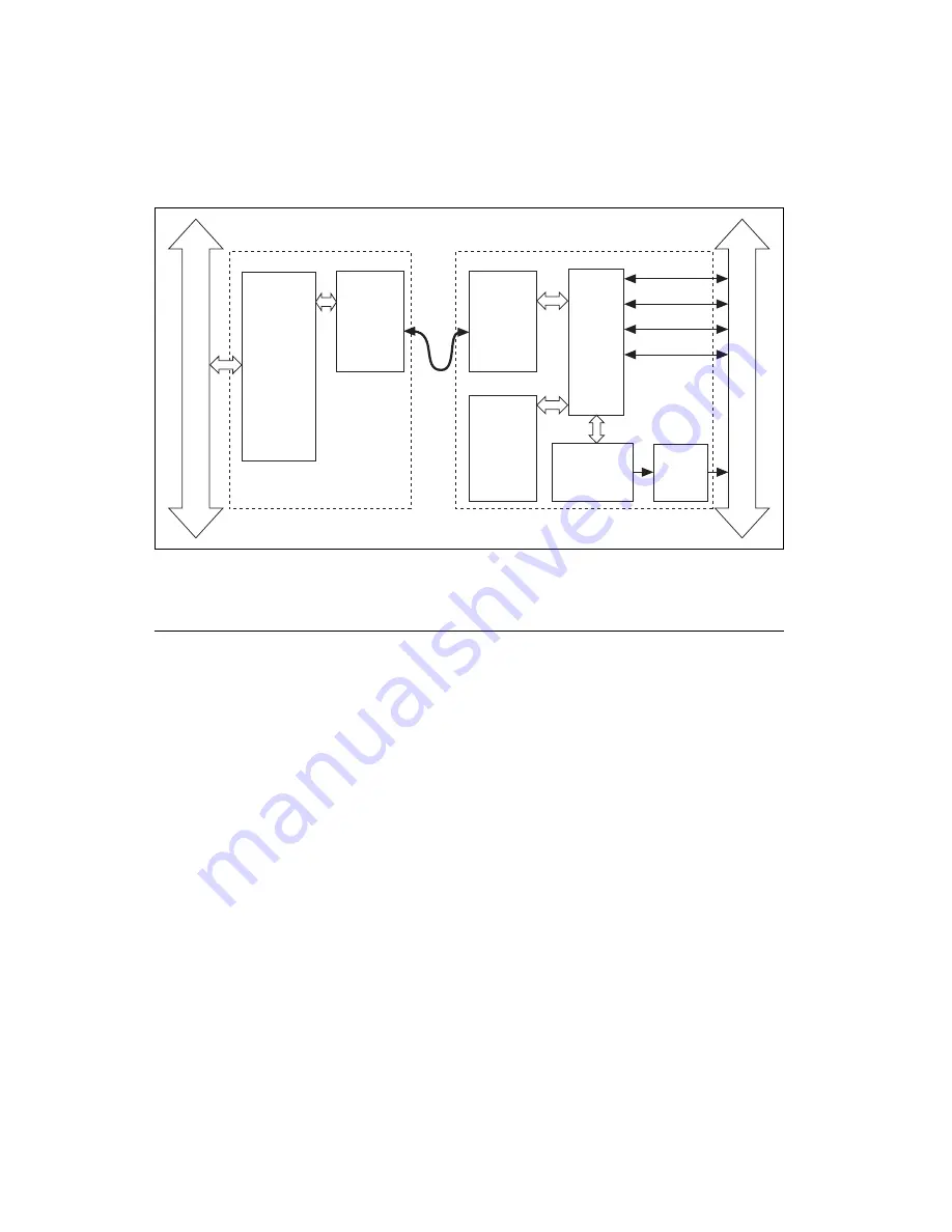
Figure 3-1.
Fiber-Optic MXI-Express x4 Block Diagram
Functional Unit Descriptions
PCI Express x4 Card Edge Connector
The card edge connector allows you to use the NI PCIe-8375 in a x4 or
wider PCI Express slot in a PC. The PCI Express Card Electromechanical
Specification defines this connector.
PCI Express Switch
The PCI Express Base Specification defines a PCI Express switch as a
logical collection of PCI Express-to-PCI Express bridge devices. On the
NI PCIe-8375, the upstream port of the switch is connected to the
PCI Express x4 card edge connector, and the downstream port is connected
to the cabled Fiber-Optic MXI-Express x4 connector.
On the NI PXIe-8375, the upstream port of the switch is connected to the
cable PORT 1. One downstream port is connected to the SMBus Master,
and four x4 ports or two x8 ports are connected to the backplane,
depending on the chassis backplane configuration. There also is a
downstream Fiber-Optic MXIe port on the front panel (PORT 2) connected
to the PCI Express switch for daisy chaining.
NI PCIe-
83
75
PCI
Express
Switch
NI PXIe-
83
75
SMBus
Master
PCI Express
to
PCI Bridge
PCI EXPRESS
PXI EXPRESS BA
CKPLANE
PCI
Express
Switch
4 x4 PCIe links or
2 x
8
PCIe links
Fiber
Optic
MXI
Express
x4
Connector
Fiber
Optic
MXI
Express
x4
Connector
Fiber
Optic
Cable
PORT 1 (upstream)
PORT 2 (downstream)
Fiber
Optic
MXI
Express
x4
Connector


