Chapter 4
Analog Input
4-20
ni.com
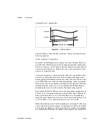
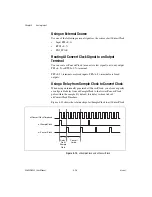
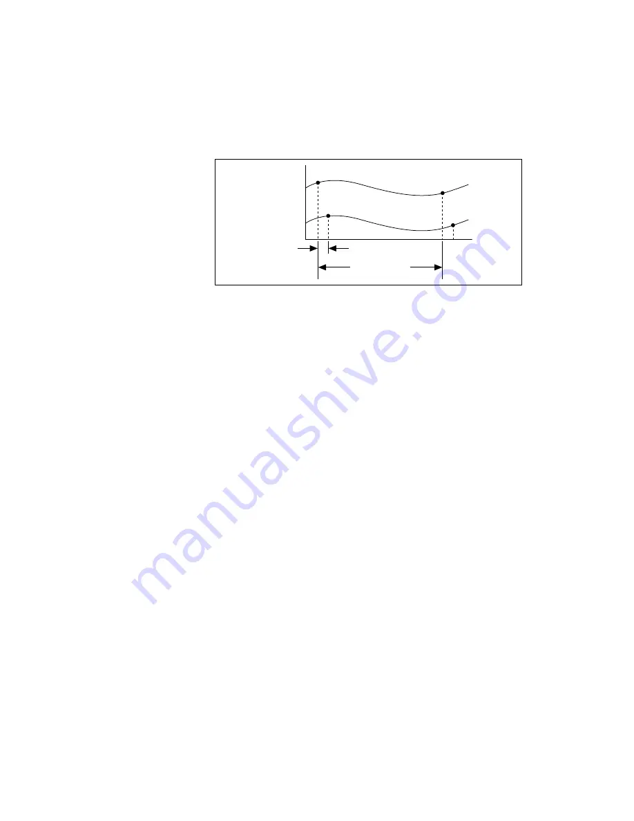
1/Sample Period = Sample Rate
Figure 4-8.
Interval Sampling
ai/ConvertClock controls the Convert Period, which is determined by the
following equation:
1/Convert Period = Convert Rate
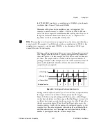
By default, the NI-DAQmx driver chooses the fastest Channel Clock rate
possible while still allowing extra time for adequate amplifier settling time.
At slower scan rates, 10
μ
s of delay is added to the fastest possible channel
conversion rate of the device, which is the same as the maximum scan rate,
to derive the Channel Clock.
As the scan rate increases, there eventually will not be enough time to have
a full 10
μ
s of additional delay time between channel conversions and to
finish acquiring all channels before the next edge of the Scan Clock. At this
point, NI-DAQmx uses round robin channel sampling, evenly dividing the
time between scans by the number of channels being acquired to obtain the
interchannel delay. In this case, you can calculate the Channel Clock by
multiplying the scan rate by the number of channels being acquired.
For example, the NI 623
x
M Series device has a maximum sampling rate of
250 kS/s. At a slower acquisition rate, such as 10 kHz with 2 channels, the
Convert Clock would be set to 71428.6 Hz. This rate is determined by
taking the fastest channel conversion rate for the device and adding 10
μ
s,
4
μ
s (1/250000) + 10
μ
s, which results in 14
μ
s or 71428.6 Hz.
When this calculation results in the sampling rate exceeding 35 kHz, there
is not enough time between samples to acquire both channels and still add
a 10
μ
s delay per channel, so the Convert Clock rate becomes the sampling
rate multiplied by the number of channels being acquired. For example, on
Channel 0
Channel 1
Convert Period
Sample Period


