Chapter 4
Analog Input
4-26
ni.com
Using an External Source
Use one of the following external signals as the source of ai/ConvertClock:
•
Input PFI <0..5>
•
RTSI <0..7>
•
PXI_STAR
Routing AI Convert Clock Signal to an Output
Terminal
You can route ai/ConvertClock (as an active low signal) out to any output
PFI <6..9> or RTSI <0..7> terminal.
PFI <0..5> terminals are fixed inputs. PFI <6..9> terminals are fixed
outputs.
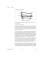
Using a Delay from Sample Clock to Convert Clock
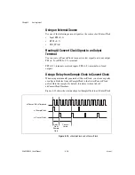
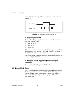
When using an internally generated ai/ConvertClock, you also can specify
a configurable delay from ai/SampleClock to the first ai/ConvertClock
pulse within the sample. By default, this delay is three ticks of
ai/ConvertClockTimebase.
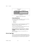
Figure 4-12 shows the relationship of ai/SampleClock to ai/ConvertClock.
Figure 4-12.
ai/SampleClock and ai/ConvertClock
ai/ConvertClockTimebase
ai/SampleClock
ai/ConvertClock
Delay
From
Sample
Clock
Convert
Period

