Chapter 8
PFI
8-2
ni.com
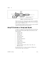
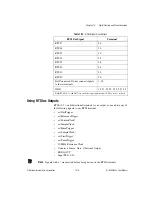
Figure 8-2.
NI 6232/6233 PFI Output Circuitry
When a terminal is used as a timing input or output signal, it is called PFI
x
(where
x
is an integer from 0 to 9). When a terminal is used as a static digital
input or output, it is called P0.
x
or P1.
x
.
The voltage input and output levels and the current drive levels of the PFI
signals are listed in the
NI 6232/6233 Specifications
.
Using PFI Terminals as Timing Input Signals
Use PFI <0..5> terminals to route external timing signals to many different
M Series functions. Each input PFI terminal can be routed to any of the
following signals.
•
AI Convert Clock
•
AI Sample Clock
•
AI Start Trigger
•
AI Reference Trigger
•
AI Pause Trigger
•
AI Sample Clock Timebase
•
AO Start Trigger
•
AO Sample Clock
•
AO Sample Clock Timebase
•
AO Pause Trigger
•
Counter input signals for either counter—Source, Gate, Aux,
HW_Arm, A, B, Z
Most functions allow you to configure the polarity of PFI inputs and
whether the input is edge or level sensitive.
Timing Signals
I/O Protection
PFI <6..9>/P1.<0..3>
Output
Enable
Static DO
Buffer
Isolation
Barrier
Digital
Isolators
Note
: One output enable is shared
by all digital output signals.

