NI 9144 User Guide and Specifications
|
© National Instruments
|
73
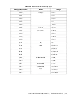
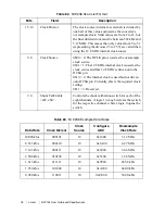
NI 9234 Example Data Rates
The example data rates use a 12.8 MHz clock source.
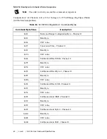
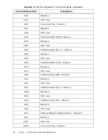
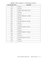
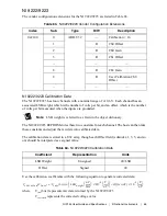
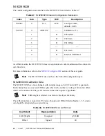
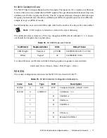
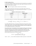
NI 9234 Calibration Data
The NI 9234 has four channels with a nominal range of ± 5 V. Each channel has an associated
AC or DC input mode; an optional IEPE excitation; an associated LSB weight, which is how
many volts there are per bit; and an offset, which is the volts per bit measured with the inputs
grounded.
Note
LSB weight is referred to as Gain in the object dictionary.
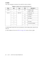
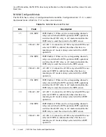
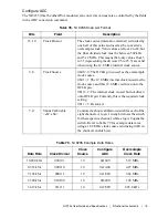
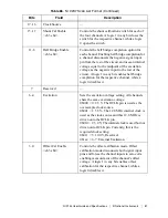
7
Reserved
—
6..2
Clock
Divisor
Clock Divisor: The NI 9234 divides the clock source
(internal or external) by this value and uses it as the
converters’ oversample clock. The data rate is equal to
1/256 times this oversample clock frequency. Valid values
for Clock Divisor are from 1 to 31, and the final divided
clock must be between 100 KHz and 12.8 MHz.
1..0
Clock Source
0b00 = 0: The OCLK pin is used as the oversample clock
source.
0b01 = 1: The 12.8 MHz internal clock is used as the clock
source and this 12.8 MHz is driven onto the OCLK pin.
0b10 = 2: The internal clock is used but not driven onto
OCLK pin. Currently, this is the required clock setting.
0b11 = 3: Reserved.
Table 75.
NI 9234 Example Data Rates
Data Rate
Clock Divisor
Clock Source
Rate Byte
Oversample
Clock Rate
50.000 kS/s
00001
10
0x06
12.80 MHz
25.000 kS/s
00010
10
0x0A
6.40 MHz
16.667 kS/s
00011
10
0x0E
4.27 MHz
12.500 kS/s
00100
10
0x12
3.20 MHz
10.000 kS/s
00101
10
0x16
2.56 MHz
6.250 kS/s
01000
10
0x22
1.60 MHz
5.000 kS/s
01010
10
0x2A
1.28 MHz
Table 74.
NI 9234 Scan List Format (Continued)
Bits
Field
Description

