background image

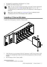
3. Align the C Series module with a slot and seat it in the slot until the latches lock in place.

Removing C Series Modules

Verify that power is not connected to the I/O connector(s) on the C Series module before you

remove a module from the NI 9144. If the system is in a nonhazardous location, the NI 9144

can be powered on when you remove modules.

Connecting the NI 9144

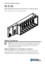
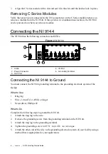
The NI 9144 has the following connectors and LEDs.

Figure 2.

 NI 9144

2

1

5

3

4

1. LEDs
2. Power Connector
3. OUT Port

4. IN Port
5. Grounding Terminal

Connecting the NI 9144 to Ground

You must connect the NI 9144 grounding terminal to the grounding electrode system of the

facility.

What to Use

Ring lug

Wire, 2.0 mm

2

 (14 AWG) or larger

Screwdriver, Phillips #2

What to Do

Complete the following steps to ground the NI 9144.
1. Attach the ring lug to the wire.
2. Remove the grounding screw from the grounding terminal on the NI 9144.
3. Attach the ring lug to the grounding terminal.
4. Tighten the grounding screw to 0.5 N · m (4.4 lb · in.) of torque.
5. Attach the other end of the wire to the grounding electrode system of your facility using a

method that is appropriate for your application.

6

  | 

ni.com

  | 

NI 9144 Getting Started Guide

Summary of Contents for NI 9144

Page 1: ...NI 9144...

Page 2: ...ult in a hazard You can compromise the safety protection built into the product if the product is damaged in any way If the product is damaged return it to NI for repair Safety Guidelines for Hazardou...

Page 3: ...ambient temperatures of 40 C Ta 70 C Caution You must make sure that transient disturbances do not exceed 140 of the rated voltage Caution The system shall only be used in an area of not more than Pol...

Page 4: ...yd s Register LR Type Approved for marine shipboard applications To verify Lloyd s Register certification for a product visit ni com certification and search for the LR certificate or look for the Llo...

Page 5: ...3 Unpack any other items and documentation from the kit Store the device in the antistatic package when the device is not in use Verifying the Kit Contents Verify that the following items are included...

Page 6: ...o the user manual on ni com manuals for more information about integrating the NI 9144 with a third party master controller Installing C Series Modules Complete the following steps to install a C Seri...

Page 7: ...ort 5 Grounding Terminal Connecting the NI 9144 to Ground You must connect the NI 9144 grounding terminal to the grounding electrode system of the facility What to Use Ring lug Wire 2 0 mm2 14 AWG or...

Page 8: ...lists the POWER LED indicators Table 1 POWER LED Indicators LED Color LED Pattern Indication Green Solid The NI 9144 is powered on and the connected power supply is adequate Off The NI 9144 is powere...

Page 9: ...setup information NI recommends that you install a private network segment for your deterministic Ethernet expansion devices Slave devices cause network flooding on a standard network Non EtherCAT fr...

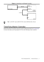
Page 10: ...hernet EtherCat Tip Use the OUT port on the NI 9144 to connect additional slave chassis Third Party Master Controller Refer to the EtherCAT Expansion Chassis Vendor Configurations Guide on ni com manu...

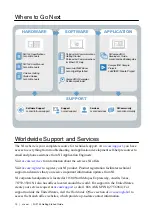
Page 11: ...i com support you have access to everything from troubleshooting and application development self help resources to email and phone assistance from NI Application Engineers Visit ni com services for i...

Page 12: ...s EULAs and third party legal notices in the readme file for your NI product Refer to the Export Compliance Information at ni com legal export compliance for the NI global trade compliance policy and...

Reviews: