background image

©

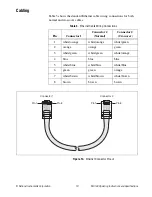
 National Instruments Corporation

13

NI 9148 Operating Instructions and Specifications

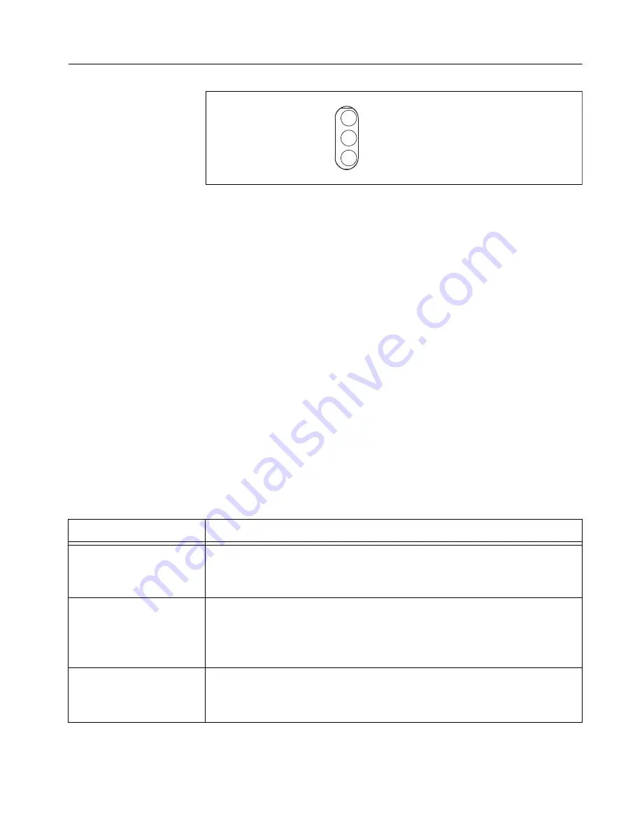
Understanding LED Indications

Figure 13.  

NI 9148 LEDs

POWER LED

The POWER


LED is lit while the NI 9148


is powered on. This LED 

indicates that the power supply connected to the chassis


is adequate.

USER FPGA1 LED

You can use the USER FPGA LED to help debug your application or easily 
retrieve application status. Use the LabVIEW FPGA Module and NI-RIO 
software to define the USER FPGA1 LED to meet the needs of your 
application. Refer to 

LabVIEW Help

 for information about programming 

this LED.

STATUS LED

The STATUS LED is off during normal operation. The NI 9148


indicates 

specific error conditions by flashing the STATUS LED a certain number of 
times every few seconds, as shown in Table 2.

Table 2.  

Status LED Indications

Number of Flashes

Indication

1

The chassis is unconfigured. Use MAX to configure the chassis. Refer 
to the 

Measurement & Automation Explorer Help 

for information about 

configuring the chassis.

2

The chassis


has detected an error in its software. This usually occurs 

when an attempt to upgrade the software is interrupted. Reinstall 
software on the chassis. Refer to the 

Measurement & Automation 

Explorer Help

 for information about installing software on the chassis.

3

The chassis is in safe mode because the SAFE MODE DIP switch is in 
the ON position. Refer to the 

Configuring DIP Switches

 section for 

information about the SAFE MODE DIP switch.

POWER
USER FPGA1
STATUS

Summary of Contents for NI 9148

Page 1: ...is document describes how to connect the NI 9148 to a network and how to use the features of the NI 9148 This document also contains specifications for the NI 9148 1 LEDs 2 RJ 45 Ethernet Port 3 Power...

Page 2: ...C Series I O modules DIN rail mount kit for DIN rail mounting only Two M4 or number 10 panhead screws for panel mounting only A number 2 Phillips screwdriver Power supply Notes Visit ni com info and...

Page 3: ...ing clearance for common connectors such as the 10 terminal detachable screw terminal connector as shown in Figure 2 Figure 2 NI 9148 Bottom View with Dimensions Figure 3 NI 9148 Front View with Dimen...

Page 4: ...on Make sure that no I O modules are in the chassis before mounting it Mounting the Chassis on a Panel You can use the NI 9905 panel mount kit to mount the NI 9148 on a flat surface Complete the follo...

Page 5: ...the NI 9905 panel to the wall using the screwdriver and screws that are appropriate for the wall surface Caution Make sure that no I O modules are in the chassis before removing it from the panel 31...

Page 6: ...n a DIN rail You need one clip for mounting the chassis on a standard 35 mm DIN rail Complete the following steps to mount the chassis on a DIN rail 1 Fasten the DIN rail clip to the chassis using a n...

Page 7: ...ly on the chassis to compress the spring until the clip locks in place on the DIN rail Caution Make sure that no I O modules are in the chassis before removing it from the DIN rail Installing C Series...

Page 8: ...when you install I O modules 2 Align the I O module with an I O module slot in the chassis as shown in Figure 10 The module slots are labeled 1 to 8 left to right Figure 10 Installing an I O Module i...

Page 9: ...net cable If you need to build your own cable refer to the Cabling section for more information about Ethernet cable wiring connections Note You will configure the IP settings as described in the Conf...

Page 10: ...COMBICON connector on the front panel of the NI 9148 Caution The C terminals are internally connected to each other Powering On the NI 9148 When you apply power to the NI 9148 the chassis runs a power...

Page 11: ...is in the IP Settings section then click Apply Note For information about configuring network settings refer to the Configuring Network Settings book of the MAX Remote Systems Help In MAX click Help H...

Page 12: ...essential services required for updating configuration and installing software Push the SAFE MODE switch to the ON position if the software on the chassis is corrupted Even if the switch is not in the...

Page 13: ...n The NI 9148 indicates specific error conditions by flashing the STATUS LED a certain number of times every few seconds as shown in Table 2 Table 2 Status LED Indications Number of Flashes Indication...

Page 14: ...ition 2 Disconnect and reconnect chassis power 3 Move the IP RESET and SAFE MODE switches to the OFF position 4 Configure the IP and other network settings in MAX Note If the chassis is restored to th...

Page 15: ...egment Reconfigurable FPGA Number of logic cells 46 080 Available embedded RAM 720 kbits Power Requirements Caution You must use a UL Listed ITE power supply marked LPS with the NI 9148 Recommended po...

Page 16: ...electronics Caution Do not connect the system to signals or use for measurements within Measurement Categories II III or IV Safety Standards This product meets the requirements of the following standa...

Page 17: ...page at ni com environment This page contains the environmental regulations and directives with which NI complies as well as other environmental information not included in this document Waste Electri...

Page 18: ...EC 60068 2 2 40 to 85 C Ingress protection IP 40 Operating humidity IEC 60068 2 56 10 to 90 RH noncondensing Storage humidity IEC 60068 2 56 5 to 95 RH noncondensing Maximum altitude 2 000 m Pollution...

Page 19: ...thernet Connector Pinout Table 3 Ethernet Cable Wiring Connections Pin Connector 1 Connector 2 Normal Connector 2 Crossover 1 white orange white orange white green 2 orange orange green 3 white green...

Page 20: ...rth Mopac Expressway Austin Texas 78759 3504 National Instruments also has offices located around the world to help address your support needs For telephone support in the United States create your se...

Reviews: