


NI 9148 Operating Instructions and Specifications
18
ni.com
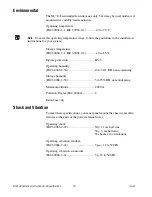
Environmental
The NI 9148 is intended for indoor use only, but it may be used outdoors if
mounted in a suitably rated enclosure.
Operating temperature
(IEC 60068-2-1, IEC 60068-2-2) ...........–40 to 70 °C
Note
To meet this operating temperature range, follow the guidelines in the installation
instructions for your system.
Storage temperature
(IEC 60068-2-1, IEC 60068-2-2) ...........–40 to 85 °C
Ingress protection ...................................IP 40
Operating humidity
(IEC 60068-2-56) ...................................10 to 90% RH, noncondensing
Storage humidity
(IEC 60068-2-56) ...................................5 to 95% RH, noncondensing
Maximum altitude...................................2,000 m
Pollution Degree (IEC 60664) ................2
Indoor use only
Shock and Vibration
To meet these specifications, you must panel mount the chassis and affix
ferrules to the ends of the power terminal wires.
Operating shock
(IEC 60068-2-27) ...................................30 g, 11 ms half sine
50 g, 3 ms half sine,
18 shocks at 6 orientations
Operating vibration, random
(IEC 60068-2-64) ...................................5 g
rms
, 10 to 500 Hz
Operating vibration, sinusoidal
(IEC 60068-2-6) .....................................5 g, 10 to 500 Hz


