NI 9401 Operating Instructions and Specifications
8
ni.com
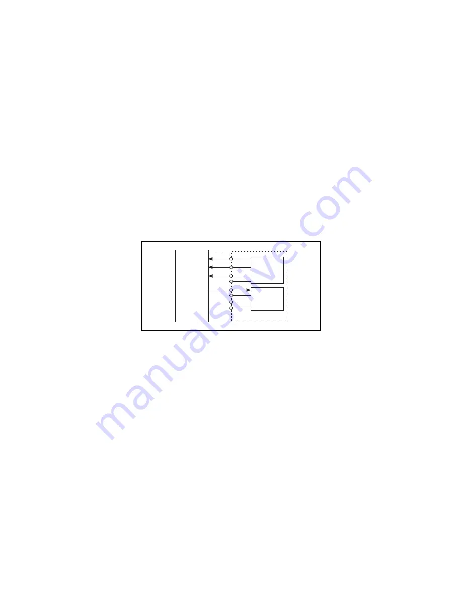
Fig
u
re 2 ill
u
strates how to connect an SPI device to the NI 9401.
In this example, the three channels assigned to o
u
tp
u
t signals are
on one port and the channel assigned to an inp
u
t signal is on the
other port.
Figure 2.
Connecting an SPI Device to the NI 9401
NI 9401
DIO3:0
Configured
for Output
DIO7:4
Configured
for Input
SCLK
MOSI
MISO
SS
SPI Device


