
Getting Started with the NI 9502 and AKM Motors
10
ni.com
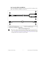
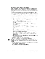
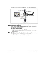
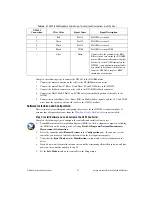
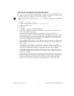
Tables 2, 3, and 4 provide the NI 9502 to AKM Motor cable screw terminal lead descriptions for the
motor, encoder, and Hall Effect sensor connections, respectively. Tables 2 and 4 show NI 9502
connections, and Table 3 shows an example NI 9411 connection.
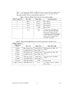
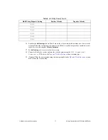
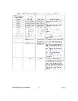
Table 2.
NI 9502 to AKM Motor Connector Screw Terminal Lead Descriptions
NI 9502 Connection
Wire Color
Signal Name
Signal Description
0
Black
Phase U
Motor Phase U.
1
White
Phase V
Motor Phase V.
2
Red
Phase W
Motor Phase W.
7
Green
COM
Motor COM.
—
Clear
Drain
Connected to the NI AKM motor
case. NI recommends leaving the
drain wire disconnected; some
applications may find it beneficial to
connect the drain wire to the NI 9502
chassis ground to improve EMC
immunity or emissions.
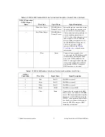
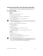
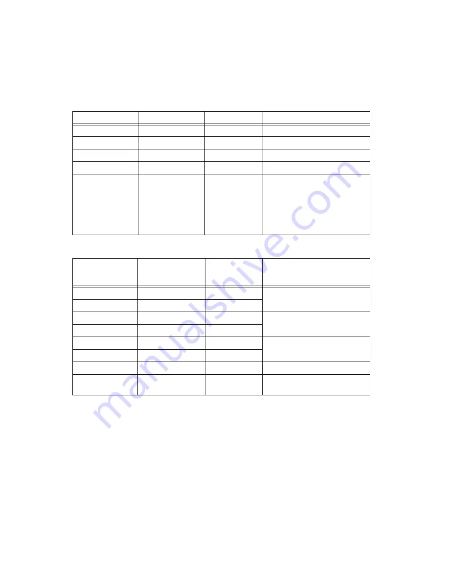
Table 3.
NI 9502 to AKM Feedback Cable Screw Terminal Lead Descriptions (Encoder Portion)
NI 9411 Connection
(NI 9411 Signal
Name)
Wire Color
Signal Name
Signal Description
1 (DI0a)
White/Orange Stripes
Encoder Phase A
Differential encoder Phase A/A–
signals.
9 (DI0b)
Orange/White Stripes
Encoder Phase A–
2 (DI1a)
White/Blue Stripes
Encoder Phase B
Differential encoder Phase B/B–
signals.
10 (DI1b)
Blue/White Stripes
Encoder Phase B–
3 (DI2a)
White/Green Stripes
Encoder Index
Differential encoder Index/Index–
signals.
11 (DI2b)
Green/White Stripes
Encoder Index–
12 (COM)
White/Brown Stripes
COM
Encoder ground.
4 (Supply (+5 Vout))
Brown/White Stripes
+5 V
+5 V supply for encoder and Hall
Effect sensors.
Summary of Contents for NI 9502
Page 1: ...NI 9502...


