
©
National Instruments Corporation
25
Getting Started with the NI 9502 and AKM Motors
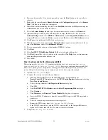
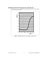
Tuning Using the Field Oriented Control Commutation Example
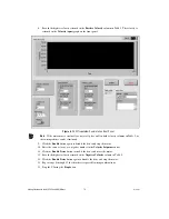
The
Velocity FOC
example project provides a tuning VI with a step response that spins the motor at
low velocity and high velocity for the specified number of samples to evaluate the step response of the
system. The following steps will help you get started with tuning your system.
Note
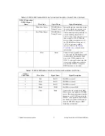
The default current gains for the
Velocity FOC
example are preconfigured for the NI AKM
motors.
1.
Run the
2 - Tune Velocity
VI.
2.
Load the file obtained from executing the
1 - AutoPhasing
VI.
3.
Connect a load to the motor.
4.
Set
Ki
to 0.
5.
Set the
Kp
to a low number, and click the
Step
button.
6.
Observe the step response and slowly increase the value of Kp until the step response begins to
oscillate around the velocity setpoint.
The proportional gain (Kp) determines the contribution of restoring force that is directly
proportional to the position error. This restoring force functions in much the same way as a spring
in a mechanical system. A system with too small a value of Kp is unable to hold position and is
very soft. Increasing Kp stiffens the axis and improves its disturbance torque rejection. However,
too large a value of Kp often results in instability.
7.
Keeping the proportional gain value set at the value determined in the previous step, set
Ki
to a low
number, and slowly increase until the velocity returned is the same as the velocity setpoint, with
little oscillation.
The integral gain (Ki) determines the contribution of restoring force that increases with time,
ensuring that the static position error in the servo loop is forced to zero. This restoring force works
against constant torque loads to help achieve zero position error when the axis is stopped.
In applications with small static torque loads, this value can be left at its default value of zero (0).
For systems having high static torque loads, this value should be tuned to minimize position error
when the axis is stopped.
Although non-zero values of Ki cause reduced static position error, they tend to cause increased
position error during acceleration and deceleration. This effect can be mitigated through the use of
the Integration Limit parameter. Too high a value of Ki often results in servo loop instability.
8.
If necessary, tune the current loop using the same tuning principles as for the velocity loop.
Summary of Contents for NI 9502
Page 1: ...NI 9502...


