
LabVIEW, National Instruments, NI, ni.com, the National Instruments corporate logo, and the Eagle
logo are trademarks of National Instruments Corporation. Refer to the
Trademark Information
at
ni.com/trademarks
for other National Instruments trademarks. Other product and company
names mentioned herein are trademarks or trade names of their respective companies. For patents
covering National Instruments products/technology, refer to the appropriate location:
Help»Patents
in your software, the
patents.txt
file on your media, or the
National Instruments Patent Notice
at
ni.com/patents
. Refer to the
Export Compliance Information
at
ni.com/legal/
export-compliance
for the National Instruments global trade compliance policy and how to
obtain relevant HTS codes, ECCNs, and other import/export data.
© 2011 National Instruments Corporation. All rights reserved.
375762A-01
Oct11
Related Documentation
The following documents contain additional information that you may find helpful. All referenced
documents ship with the product and are available at
ni.com/manuals
.
•
NI 9502 Operating Instructions and Specifications
—Use this document to learn additional
information about the NI 9502 including detailed specifications and important safety information.
•
Operating instructions for the real-time controller.
•
LabVIEW NI SoftMotion Module Help
—Use this help file to learn about using the NI SoftMotion
Module in LabVIEW including information about the Motor Control VIs and using the
NI SoftMotion Module with the LabVIEW Project. To access this help file from LabVIEW,
select
Help»LabVIEW Help
, then expand the
LabVIEW NI SoftMotion Module
book on the
Contents
tab.
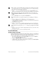
Worldwide Support and Services
The National Instruments Web site is your complete resource for technical support. At
ni.com/
support
you have access to everything from troubleshooting and application development self-help
resources to email and phone assistance from NI Application Engineers.
Visit
ni.com/services
for NI Factory Installation Services, repairs, extended warranty, calibration,
and other services.
Visit
ni.com/register
to register your National Instruments product. Product registration facilitates
technical support and ensures that you receive important information updates from NI.
A Declaration of Conformity (DoC) is our claim of compliance with the Council of the European
Communities using the manufacturer’s declaration of conformity. This system affords the user
protection for electromagnetic compatibility (EMC) and product safety. You can obtain the DoC for
your product by visiting
ni.com/certification
. If your product supports calibration, you can
obtain the calibration certificate for your product at
ni.com/calibration
.
National Instruments corporate headquarters is located at 11500 North Mopac Expressway, Austin,
Texas, 78759-3504. National Instruments also has offices located around the world to help address your
support needs. For telephone support in the United States, create your service request at
ni.com/
support
and follow the calling instructions or dial 512 795 8248. For telephone support outside the
United States, visit the Worldwide Offices section of
ni.com/niglobal
to access the branch office
Web sites, which provide up-to-date contact information, support phone numbers, email addresses, and
current events.
Summary of Contents for NI 9502
Page 1: ...NI 9502...


