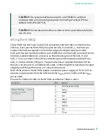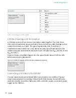
Connector
Pin
Signal
1
No Connection (NC)
2
CAN_L
3
COM0
4
NC
5
SHLD
6
COM0
7
CAN_H
8
NC
9
V
SUP0
Table 2. Pin Assignments for CAN1
CAN Bus Topology and Termination
A CAN bus consists of two or more CAN nodes cabled together. The CAN_H and
CAN_L pins of each node are connected to the main CAN bus cable through a short
connection known as a “stub.” The pair of signal wires, CAN_H and CAN_L,
constitutes a transmission line. Every device on a low-speed/fault-tolerant CAN
network requires a termination resistor for each CAN data line: R
RTH
for CAN_H and
R
RTL
for CAN_L.
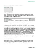
Figure 1 shows a simplified diagram of a low-speed/fault-tolerant CAN bus with
termination resistor placements.
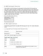
Figure 1. CAN Bus Topology and Termination Resistor Locations
Connecting a CAN Bus to the NI 9852
You can connect each port of the NI 9852 to any location on a CAN bus. Figure 2
shows one example of connecting CAN0 of the NI 9852 directly to one CAN node,
and CAN1 directly to another CAN node. CAN0 and CAN1 require an external power
supply on the CAN bus.
ni.com
6
NI-9852 Getting Started


