©
National Instruments Corporation
5
NI 9925 Installation Guide
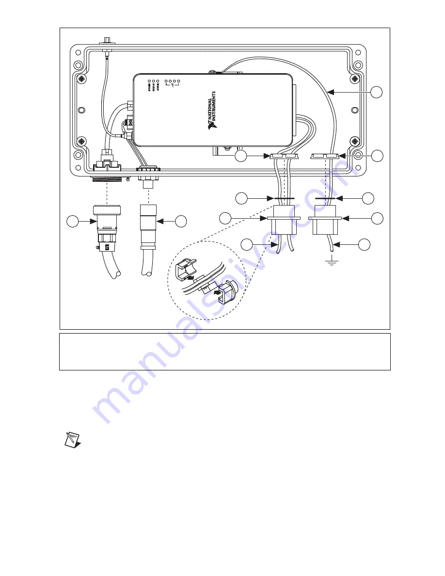
Figure 7.
Connecting External Cables/Components
15. Connect an external IP rated M12 power cable to the external M12 power connector on the
NI 9925 as shown in Figure 7. Refer to the
IP Rated Cables
section for information about
ordering and making custom IP rated M12 power cables.
Note
When either the external M12 power connector or external Ethernet connector
on the NI 9925 is not in use, cover that connector with the compatible end cap.
16. Connect the I/O cable(s) from the C Series module and route through one or both of the
I/O openings. Refer to the
IP Rated Cables
section for information about making and
connecting IP rated I/O cables.
17. Connect a ground wire to the chassis ground screw on the cDAQ chassis as described in the
NI cDAQ-918x/919x User Manual
. Route the ground wire through one of the I/O openings,
1
External RJ45 Ethernet Cable
2
External M12 Power Cable
3
I/O Cables
4
I/O Cable Clamps and Grommets
5
I/O Cable Clamp Gaskets
6
I/O Cable Clamp Nut
7
Ground Wire
2
1
6
5
5
4
4
3
3
7
6