


NI 9925 Installation Guide
6
ni.com
as described in the
Building IP Rated I/O Cables
section. Terminate the ground wire to the
nearest earth ground or grounded structure.
Caution
For I/O openings on the NI 9925 that are not in use, use the blank grommets
in the cable clamps to seal the openings and maintain an IP54 rating.
18. Reattach the enclosure cover by tightening the captive screws with a number 2 Phillips
screwdriver.
IP Rated Cables
This section contains information about using the field termination connectors that are shipped
in the NI 9925 outdoor IP enclosure kit to make your own cable lengths. You can order IP rated
cables and accessories from NI.
Building an IP Rated M12 Power Field Termination Cable
One M12 power female field termination connector kit is included in the NI 9925 kit for creating
a custom M12 power cable. To build an M12 field termination cable, complete the following
steps.
Caution
Only use the connectors provided with the NI 9925 to build your cables.
Note
Be sure to route the wires through the plastic and rubber sealing grommets and
the backshell before connecting to the screw terminals on the M12 field termination
connector.
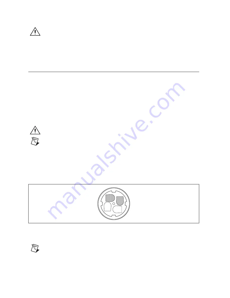
1.
Build the M12 power female field termination connector by connecting the positive lead of
the primary power supply to Pin 4. The pin number is marked on the inside of the field
termination connector, next to the respective terminal, as shown in Figure 8.
Figure 8.
M12 Power Female Field Termination Connector Pinout
2.
Connect the negative lead to Pin 3, as shown in Figure 8.
Note
When the external M12 power connector on the NI 9925 is not in use, cover
the connector with the M12 power end cap.
1
2
3
4
+
–


