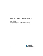
background image

NI cDAQ

TM

-9181/9184/9188/9191

User Manual

NI CompactDAQ Ethernet and Ethernet/Wireless Chassis

NI cDAQ-9181/9184/9188/9191 User Manual

February 2017
372780K-01

Summary of Contents for NI cDAQ-9181

Page 1: ...NI cDAQ TM 9181 9184 9188 9191 User Manual NI CompactDAQ Ethernet and Ethernet Wireless Chassis NI cDAQ 9181 9184 9188 9191 User Manual February 2017 372780K 01...

Page 2: ...port phone numbers email addresses and current events National Instruments Corporate Headquarters 11500 North Mopac Expressway Austin Texas 78759 3504 USA Tel 512 683 0100 For further support informat...

Page 3: ...TLE OR NON INFRINGEMENT AND ANY WARRANTIES THAT MAY ARISE FROM USAGE OF TRADE OR COURSE OF DEALING NI DOES NOT WARRANT GUARANTEE OR MAKE ANY REPRESENTATIONS REGARDING THE USE OF OR THE RESULTS OF THE...

Page 4: ...ependent from NI and have no agency partnership or joint venture relationship with NI Patents For patents covering NI products technology refer to the appropriate location Help Patents in your softwar...

Page 5: ...AQ Chassis on a Desktop 1 17 NI 9901 Desktop Kit for cDAQ 9184 9188 Chassis 1 17 Mounting the cDAQ Chassis on a Panel 1 17 cDAQ 9181 9191 1 18 cDAQ 9184 9188 1 21 Mounting the cDAQ Chassis on a DIN Ra...

Page 6: ...2 6 Using an Analog Source 2 6 Routing the Reference Trigger Signal to an Output Terminal 2 6 AI Pause Trigger Signal 2 7 Using a Digital Source 2 7 Using an Analog Source 2 7 Getting Started with AI...

Page 7: ...ing Signals 4 10 Digital Output Timing Signals 4 10 Getting Started with DO Applications in Software 4 13 Digital Input Output Configuration for NI 9401 4 13 PFI 4 13 PFI Filters 4 13 Chapter 5 Counte...

Page 8: ...lse Generation 5 24 Single Pulse Generation 5 24 Single Pulse Generation with Start Trigger 5 25 Pulse Train Generation 5 25 Finite Pulse Train Generation 5 25 Retriggerable Pulse or Pulse Train Gener...

Page 9: ...5 37 Counter n Internal Output and Counter n TC Signals 5 37 Routing Counter n Internal Output to an Output Terminal 5 37 Frequency Output Signal 5 37 Routing Frequency Output to a Terminal 5 37 Defau...

Page 10: ...e designed for use with C Series modules The cDAQ chassis are capable of measuring a broad range of analog and digital I O signals and sensors For module specifications refer to the documentation incl...

Page 11: ...s Module 3 Module Slots 4 Ethernet Port LINK ACT and 10 100 1000 LEDs 5 Power Connector 6 Reset Button 7 POWER STATUS and ACTIVE LEDs 1 Chassis Grounding Screw 2 Installed C Series Module 3 Module Slo...

Page 12: ...rovide reasonable protection against harmful interference when the product is operated in the intended operational electromagnetic environment This product is intended for use in industrial locations...

Page 13: ...following symbols are marked on your cDAQ chassis Caution When this symbol is marked on a product refer to the Safety Guidelines section for information about precautions to take ESD When this symbol...

Page 14: ...atic package when the chassis is not in use Installing the cDAQ Chassis The cDAQ chassis and C Series module s are packaged separately For an interactive demonstration of how to install the cDAQ chass...

Page 15: ...alling your software go to ni com support daqmx Note Table 1 1 lists the earliest NI DAQmx support version for each cDAQ Ethernet and wireless chassis The NI DAQmx software is included on the disk shi...

Page 16: ...ds to the chassis grounding screw shown in Figure 1 4 unless otherwise specified in the C Series module documentation Refer to the Chassis Grounding Screw section for more information about making thi...

Page 17: ...as long as power is being supplied to the cDAQ chassis The STATUS LED turns off after firmware boots Refer to the LEDs section for information about the LEDs on the cDAQ chassis 15 cDAQ 9191 If you wa...

Page 18: ...ork you may first need to upload a certificate by clicking Certificate Management Contact your IT department if you are unsure of your network settings or configuration details Note For EAP TLS authen...

Page 19: ...ds Connected Running the cDAQ chassis is connected to the wireless network Figure 1 6 Chassis Connected Running on Ethernet and Wireless Networks Note Establishing a network connection may take severa...

Page 20: ...into the Add Device Manually field and click the button Otherwise enter the hostname of the chassis The default hostname is cDAQ91xx serial number where the xx represents the last two digits of your c...

Page 21: ...his manual and the Finding a Network DAQ Device in MAX topic in the Measurement Automation Explorer Help for NI DAQmx 17 cDAQ 9191 Disconnect the Ethernet cable from cDAQ 9191 chassis if you connected...

Page 22: ...me warm to the touch This is normal Wiring Power to the cDAQ Chassis Caution To ensure the specified EMC performance do not connect the power input to a DC mains supply or to any supply requiring a co...

Page 23: ...C terminal is not connected to chassis ground You can connect the C terminal to chassis ground externally Refer to the Power Requirements section of the specifications document for your cDAQ chassis...

Page 24: ...d automatically after it was added Add Device you can reserve the cDAQ chassis in MAX by expanding Devices and Interfaces Network Devices selecting the chassis and clicking the Reserve Chassis button...

Page 25: ...ow the cDAQ chassis for air circulation Allows at least 50 8 mm 2 in of clearance in front of the modules for common connector cabling such as the 10 terminal detachable screw terminal connector and a...

Page 26: ...crews on the back side and I O end of the chassis must be removed as shown in Figure 1 11 After removing the screws replace them with the screws included in the NI 9901 desktop mounting kit The cDAQ 9...

Page 27: ...assis Caution Remove the C Series module s from the cDAQ chassis before you mount the chassis to the panel After the cDAQ chassis is mounted you can reinsert the C Series module s Panel Mounting with...

Page 28: ...9184 9188 9191 User Manual Figure 1 12 Installing the cDAQ 9181 9191 Panel Mount Kit Figure 1 13 NI 9903 Panel Mount Accessory Dimensions 101 6 mm 4 00 in 59 7 mm 2 35 in 38 1 mm 1 5 in 14 0 mm 0 55...

Page 29: ...6 32 UNC 2B machine screws with a maximum threaded engagement length of 4 83 mm 0 190 in to go through the panel and into the back of the chassis as shown in Figure 1 14 National Instruments does not...

Page 30: ...is mounted you can reinsert the C Series module s Align the cDAQ chassis on the panel mount accessory and attach the chassis to the accessory with two screws included in the kit as shown in Figure 1 1...

Page 31: ...1 15 cDAQ 9184 9188 Panel Mount Dimensions and Installation 8 7 6 5 4 3 2 1 28 1 mm 1 11 in 48 1 mm 1 90 in 88 1 mm 3 47 in 330 2 mm 13 00 in NI cDAQ 9188 NI Compac tD AQ 27 30 mm 1 08 in 29 49 mm 1...

Page 32: ...the chassis before removing it from the surface Mounting the cDAQ Chassis on a DIN Rail Caution To maintain product performance and accuracy specifications when the ambient temperature is between 45 C...

Page 33: ...chassis using two FLH 6 32 5 16 in screws included in the kit with a number 2 Phillips screwdriver as shown in Figure 1 17 Note The threaded holes on cDAQ 9181 9191 chassis for panel or DIN rail moun...

Page 34: ...ail mounting kit contains one clip for mounting the chassis on a standard 35 mm DIN rail To mount the chassis on a DIN rail fasten the DIN rail clip to the chassis using a number 2 Phillips screwdrive...

Page 35: ...id copper wire with a maximum length of 1 5 m 5 ft Attach the wire to the earth ground of the facility s power system For more information about earth ground connections refer to the KnowledgeBase doc...

Page 36: ...A DAQ task is not running on the chassis Table 1 4 Wireless Signal Strength LED State Chassis Status LED State LED Pattern Chassis Status LED 1 on LEDs 2 through 4 off Connected to network with poor...

Page 37: ...ACT described in Table 1 5 1 You can either use a shielded straight through Category 5 Ethernet cable or an Ethernet crossover cable to connect the cDAQ chassis directly to your computer 2 10 100 LED...

Page 38: ...cables Table 1 6 Ethernet Cable Wiring Connections Pin Connector 1 Connector 2 Straight Through Crossover 1 white orange white orange white green 2 orange orange green 3 white green white green white...

Page 39: ...ation to the factory set defaults listed in Table 1 7 Power Connector Refer to the specifications document for your cDAQ chassis for information about the power connector on the cDAQ chassis PFI BNC C...

Page 40: ...chassis power can be on when you remove modules 2 Squeeze the latches on both sides of the module and pull the module out of the chassis Table 1 8 cDAQ Chassis Cables and Accessories Accessory Part N...

Page 41: ...owing you to customize the cDAQ system to meet your application needs C Series modules are hot swappable and automatically detected by the cDAQ chassis I O channels are accessible using the NI DAQmx d...

Page 42: ...to the following sections for more information about the configuration of these signals The Analog Input Timing Signals section of Chapter 2 Analog Input The Analog Output Timing Signals section of Ch...

Page 43: ...ed on the cDAQ 9188 chassis Refer to the PFI section of Chapter 4 Digital Input Output and PFI for more information Flexible Counter Timers The cDAQ chassis includes four general purpose 32 bit counte...

Page 44: ...nfigurations The three AI timing engines are ai te0 and te1 Analog Input Triggering Signals A trigger is a signal that causes an action such as starting or stopping the acquisition of data When you co...

Page 45: ...he start of a sample of all analog input channels in the task Sample Clock can be generated from external or internal sources as shown in Figure 2 1 Figure 2 1 AI Sample Clock Timing Options Routing t...

Page 46: ...specify the conversion rate use the ActiveDevs and AI Convert Clock Rate properties using the DAQmx Timing property node or functions Simultaneous Sample and Hold Modules Simultaneous sample and hold...

Page 47: ...dule in the cDAQ chassis the maximum Sample Clock rate can run faster than the maximum rate for the module When operating at a rate faster than these slow rate modules can support the slow rate module...

Page 48: ...signals as the source Any PFI terminal Counter n Internal Output The source also can be one of several other internal signals on your cDAQ chassis Refer to the Device Routing in MAX topic in the NI D...

Page 49: ...buffer contains the number of posttrigger samples desired Figure 2 3 shows the final buffer Figure 2 3 Reference Trigger Final Buffer Using a Digital Source To use Reference Trigger with a digital so...

Page 50: ...n Analog Source Some C Series modules can generate a trigger based on an analog signal In NI DAQmx this is called the Analog Comparison Event When you use an analog trigger source the internal sample...

Page 51: ...ion Methods When performing an analog output operation you either can perform software timed or hardware timed generations Hardware timed generations must be buffered Software Timed Generations With a...

Page 52: ...continuous generation continues until you stop the operation There are three different continuous generation modes that control how the data is written These modes are regeneration onboard regenerati...

Page 53: ...ing Signals The cDAQ chassis features the following AO waveform generation timing signals AO Sample Clock Signal AO Sample Clock Timebase Signal AO Start Trigger Signal AO Pause Trigger Signal Signals...

Page 54: ...the following signals A pulse initiated by host software Any PFI terminal AI Reference Trigger AI Start Trigger The source also can be one of several internal signals on the cDAQ chassis Refer to the...

Page 55: ...n in Figure 3 2 Figure 3 2 AO Pause Trigger with the Onboard Clock Source If you are using any signal other than the onboard clock as the source of the sample clock the generation resumes as soon as t...

Page 56: ...a DAC to generate a waveform you may observe glitches on the output signal These glitches are normal when a DAC switches from one voltage to another it produces glitches due to released charges The l...

Page 57: ...sis slot and can perform the following tasks Software timed and hardware timed digital input output tasks Parallel digital modules can be used in any chassis slot and can perform the following tasks S...

Page 58: ...es of digital triggering internal software digital triggering external digital triggering and internal digital triggering Three triggers are available Start Trigger Reference Trigger and Pause Trigger...

Page 59: ...inal DI Sample Clock Timebase Signal The DI Sample Clock Timebase di SampleClockTimebase signal is divided down to provide a source for DI Sample Clock DI Sample Clock Timebase can be generated from e...

Page 60: ...tware command in continuous mode An acquisition that uses a start trigger but not a reference trigger is sometimes referred to as a posttriggered acquisition That is samples are measured only after th...

Page 61: ...the specified number of pretrigger samples the chassis ignores the condition If the buffer becomes full the cDAQ chassis continuously discards the oldest samples in the buffer to make space for the n...

Page 62: ...e and a polarity The source can be either from PFI or one of several other internal signals on your cDAQ chassis Refer to the Device Routing in MAX topic in the NI DAQmx Help or the LabVIEW Help for m...

Page 63: ...ng Started with DI Applications in Software You can use the cDAQ chassis in the following digital input applications Single point acquisition Finite acquisition Continuous acquisition For more informa...

Page 64: ...o multiple software timed tasks on a single module as well as mix hardware timed and software timed digital output tasks on a single module On serial digital output modules formerly known as static di...

Page 65: ...ating a set number of data samples and stopping a continuous generation continues until you stop the operation There are three different continuous generation modes that control how the data is writte...

Page 66: ...e following DO timing signals DO Sample Clock Signal DO Sample Clock Timebase Signal DO Start Trigger Signal DO Pause Trigger Signal Signals with an support digital filtering Refer to the PFI Filters...

Page 67: ...ice Routing in MAX topic in the NI DAQmx Help or the LabVIEW Help for more information You also can specify whether the waveform generation begins on the rising edge or falling edge of DO Start Trigge...

Page 68: ...polarity The source can be a PFI signal or one of several other internal signals on the cDAQ chassis You also can specify whether the samples are paused when DO Pause Trigger is at a logic high or low...

Page 69: ...r task NI DAQmx generates an error instead of sending the line configuration command During the line configuration command the output lines are maintained without glitching PFI You can configure chann...

Page 70: ...on on an input that has a custom filter set to N 5 Figure 4 7 PFI Filter Example Table 4 1 Selectable PFI Filter Settings Filter Setting Filter Clock Jitter Min Pulse Width to Pass Max Pulse Width to...

Page 71: ...unter signals refer to the Default Counter Timer Routing section Each counter has a FIFO that can be used for buffered acquisition and generation Each counter also contains an embedded counter Embedde...

Page 72: ...son Event Not all timed counter operations require a sample clock For example a simple buffered pulse width measurement latches in data on each edge of a pulse For this measurement the measured signal...

Page 73: ...ion The counter values can be read on demand or with a sample clock Refer to the following sections for more information about edge counting options Single Point On Demand Edge Counting Buffered Sampl...

Page 74: ...the number of edges on the Source input after the counter is armed The value of the counter is sampled on each active edge of a sample clock and stored in the FIFO The STC3 transfers the sampled valu...

Page 75: ...ou can route an internal or external periodic clock signal with a known period to the Source input of the counter The counter counts the number of rising or falling edges on the Source signal while th...

Page 76: ...lse width measurement takes measurements over multiple pulses The counter counts the number of edges on the Source input while the Gate input remains active On each trailing edge of the Gate signal th...

Page 77: ...the high and low time of a pulse on its Gate input signal after the counter is armed A pulse is defined in terms of its high and low time high and low ticks or frequency and duty cycle This is similar...

Page 78: ...whether to read the high pulse or low pulse first using the StartingEdge property in NI DAQmx Figure 5 9 shows an example of an implicit buffered pulse measurement Figure 5 9 Implicit Buffered Pulse M...

Page 79: ...ck signal with a known period to the Source input of the counter The counter counts the number of rising or falling edges occurring on the Source input between two edges of the Gate signal You can cal...

Page 80: ...versus Semi Period Measurements In hardware pulse measurement and semi period are the same measurement Both measure the high and low times of a pulse The functional difference between the two measurem...

Page 81: ...ments with one counter you measure one period of your signal using a known timebase You can route the signal to measure fx to the Gate of a counter You can route a known timebase fk to the Source of t...

Page 82: ...you measure the width of pulse T to be N periods of fx the frequency of fx is N T Figure 5 13 illustrates this method Another option is to measure the width of a known period instead of a known pulse...

Page 83: ...ven by fx fk N J Sample Clocked Buffered Frequency Measurement Sample clocked buffered point frequency measurements can either be a single frequency measurement or an average between sample clocks Use...

Page 84: ...fast as the sample clock to prevent a measurement overflow Choosing a Method for Measuring Frequency The best method to measure frequency depends on several factors including the expected frequency of...

Page 85: ...counter measurement but now the user has an integer divide down of the signal An internal timebase is still used for the source frequency fk but the divide down means that the measurement time is the...

Page 86: ...e measurement times for the sample clocked with averaging and two counter frequency measurements are configured the same Table 5 3 summarizes the results Table 5 3 50 kHz Frequency Measurement Methods...

Page 87: ...ency so at 50 k and 5 M with a measurement time of 1 ms the error percentage is still close to 0 00125 One of the disadvantages of a sample clocked frequency measurement is that the frequency to be me...

Page 88: ...ternal or external periodic clock signal with a known period to the Source input of the counter The counter counts the number of rising or falling edges occurring on the Source input between the two a...

Page 89: ...ure encoders that use X1 X2 or X4 encoding A quadrature encoder can have up to three channels channels A B and Z X1 Encoding When channel A leads channel B in a quadrature cycle the counter increments...

Page 90: ...adrature encoder to obtain timing of channel Z with respect to channels A and B You must then ensure that channel Z is high during at least a portion of the phase you specify for reload For instance i...

Page 91: ...ansfers the sampled values to host memory using a high speed data stream The count values returned are the cumulative counts since the counter armed event that is the sample clock does not reset the c...

Page 92: ...ffered Two Signal Edge Separation Measurement Sample Clocked Buffered Two Signal Separation Measurement Single Two Signal Edge Separation Measurement With single two signal edge separation measurement...

Page 93: ...r counts the number of rising or falling edges on the Source input occurring between an active edge of the Gate signal and an active edge of the Aux signal The counter then stores the count in the FIF...

Page 94: ...Pulse Generation The counter can output a single pulse The pulse appears on the Counter n Internal Output signal of the counter You can specify a delay from when the counter is armed to the beginning...

Page 95: ...ure 5 27 Single Pulse Generation with Start Trigger Pulse Train Generation Refer to the following sections for more information about the cDAQ chassis pulse train generation options Finite Pulse Train...

Page 96: ...first trigger or to all triggers using the CO EnableInitalDelayOnRetrigger property The default for a single pulse is True while the default for finite pulse trains is False The counter ignores the G...

Page 97: ...ay is measured in terms of a number of active edges of the Source input You specify the high and low pulse widths of the output signal The pulse widths are also measured in terms of a number of active...

Page 98: ...frequency and duty cycle or idle ticks and active ticks Note On buffered implicit pulse trains the pulse specifications in the DAQmx Create Counter Output Channel are ignored so that you generate the...

Page 99: ...generates a predetermined number of pulse train updates Each point you write defines pulse specifications that are updated with each sample clock When a sample clock occurs the current pulse idle fol...

Page 100: ...be continually written to the buffer If the program does not write new data to the buffer at a fast enough rate to keep up with the generation the buffer underflows and causes an error Continuous Buf...

Page 101: ...or when the divider is set to 5 Figure 5 35 Frequency Generator Output Waveform Frequency Output can be routed out to any PFI terminal All PFI terminals are set to high impedance at startup The FREQ O...

Page 102: ...pulse delay will be 100 on the second it will be 110 on the third it will be 120 the process will repeat in this manner until the counter is disarmed The counter ignores any Gate edge that is receive...

Page 103: ...ource Signal The selected edge of the Counter n Source signal increments and decrements the counter value depending on the application the counter is performing Table 5 8 lists how this terminal is us...

Page 104: ...nd saving the counter contents Routing a Signal to Counter n Gate Each counter has independent input selectors for the Counter n Gate signal Any of the following signals can be routed to the Counter n...

Page 105: ...nformation about available routing options Counter n A Counter n B and Counter n Z Signals Counter n B can control the direction of counting in edge counting applications Use the A B and Z inputs to e...

Page 106: ...s may not be available in some driver software Refer to the Device Routing in MAX topic in the NI DAQmx Help or the LabVIEW Help for more information about available routing options Counter n Sample C...

Page 107: ...larity is software selectable for both options With pulse or pulse train generation tasks the counter drives the pulse s on the Counter n Internal Output signal The Counter n Internal Output signal ca...

Page 108: ...enerated and the generation stops unless you use the retriggerable attribute When you use this attribute subsequent start triggers cause the generation to restart When using a start trigger the start...

Page 109: ...Prescaling can be used for event counting provided it is acceptable to have an error of up to seven or one ticks Prescaling can be used when the counter Source is an external signal Prescaling is not...

Page 110: ...enerates a delayed Source signal by delaying the Source signal by several nanoseconds The chassis synchronizes signals on the rising edge of the delayed Source signal and counts on the following risin...

Page 111: ...nt data movement Routes timing and control signals The acquisition generation sub systems use these signals to manage acquisitions and generations These signals can come from the following sources You...

Page 112: ...y of the AI and AO timing signals It can function as the Source input to the 32 bit general purpose counter timers The 20 MHz Timebase is generated by dividing down the 80 MHz Timebase as shown in Fig...

Page 113: ...RSS 210 This device complies with Industry Canada license exempt RSS standard s Operation is subject to the following two conditions 1 this device may not cause interference and 2 this device must acc...

Page 114: ...isque d interf rence ventuelle pour les autres utilisateurs le type et le gain de l antenne doivent tre choisis de mani re ce que la puissance isotrope rayonn e quivalente p i r e minimale n cessaire...

Page 115: ...declara que el NI cDAQ 9191 cumple con los requisitos esenciales y cualesquiera otras disposiciones aplicables o exigibles de la Directiva 1999 5 CE Greek National Instruments NI cDAQ 9191 1999 5 Fra...

Page 116: ...E Slovensko Slovenian National Instruments izjavlja da je ta NI cDAQ 9191 v skladu z bistvenimi zahtevami in ostalimi relevantnimi dolo ili direktive 1999 5 ES Slovensky Slovak National Instruments t...

Page 117: ...pamento opera em car ter secund rio isto n o tem direito a prote o contra interfer ncia prejudicial mesmo de esta es do mesmo tipo e n o pode causar interfer ncia a sistemas operando em car ter prim r...

Page 118: ...r taking measurements and controlling measurement devices The following references to documents assume you have NI DAQmx 16 0 or later cDAQ Chassis Documentation The NI cDAQ 9181 Quick Start NI cDAQ 9...

Page 119: ...electing Help LabVIEW Help in LabVIEW to access information about LabVIEW programming concepts step by step instructions for using LabVIEW and reference information about LabVIEW VIs functions palette...

Page 120: ...n For help with NI DAQmx methods and properties refer to the NationalInstruments DAQmx namespace and the NationalInstruments DAQmx ComponentModel namespace For conceptual help with NI DAQmx refer to U...

Page 121: ...ning courses To enroll in a course or obtain a detailed course outline refer to ni com training Technical Support on the Web For additional support refer to ni com support or ni com examples Note You...

Page 122: ...fy your systems accuracy and reliability requirements and provides warranty sparing and calibration services to help you maintain accuracy and minimize downtime over the life of your system Visit ni c...

Page 123: ...tions Engineers make sure every question submitted online receives an answer Software Support Service Membership The Standard Service Program SSP is a renewable one year subscription included with alm...

Page 124: ...lock Timebase 3 4 AO Start Trigger 3 4 ANSI C documentation B 3 antenna 1 30 applications counter input 5 3 counter output 5 24 edge counting 5 3 arm start trigger 5 38 B buffered edge counting 5 4 ha...

Page 125: ...thods 3 1 DO generation methods 4 8 DI Sample Clock signal 4 3 digital I O change detection event 4 7 configuration for NI 9401 4 13 digital input 4 2 digital output 4 8 parallel versus serial DIO mod...

Page 126: ...se with start trigger 5 25 software timed analog output 3 1 digital output 4 8 getting started AI applications in software 2 7 AO applications in software 3 6 DI applications in software 4 7 DO applic...

Page 127: ...for ETS 5 32 train generation 5 25 continuous 5 27 pulse width measurement 5 5 implicit buffered 5 6 single 5 6 Q QoS priority 1 15 quadrature encoders 5 19 R rebooting 1 30 reciprocal frequency measu...

Page 128: ...hassis connectivity 1 14 two signal edge separation measurement 5 21 buffered 5 22 single 5 22 U uninstalling 1 31 unpacking 1 5 using the cDAQ chassis 1 32 W wireless networks 1 12 QoS priority 1 15...

Reviews: