

Using the Internal Real-Time Clock
The system clock of the cRIO-9074XT is synchronized with the internal high-precision real-
time clock at startup. This synchronization provides timestamp data to the controller. You can
also use the internal real-time clock to correct drift of the system clock. Refer to the
Real-Time Clock Specifications
for the accuracy specifications of the real-time clock.
Using the SMB Connector for Digital I/O
(cRIO-9074 only)
You can use the SMB connector of the cRIO-9074XT to connect digital devices to the
controller. For example, if you connect the pulse-per-second output of a GPS device to the
SMB connector of the cRIO-9074XT, you can use the GPS device to correct for drift of the
system clock.
For software that supports GPS drift-correction and other digital I/O through the SMB
connector, go to
and enter the Info Code
criosmb
.
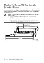
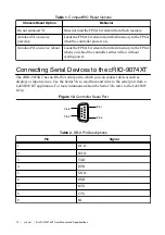
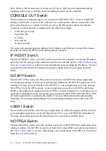
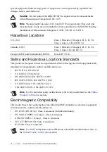
Configuring DIP Switches
Figure 13.
DIP Switches
1
6
5
4
3
2
SAFE MODE
CONSOLE OUT
IP RESET
NO APP
USER1
NO FPGA
OFF
All of the DIP switches are in the OFF position when the chassis is shipped from National
Instruments.
SAFE MODE Switch
The position of the SAFE MODE switch determines whether the embedded LabVIEW Real-
Time engine launches at startup. If the switch is in the OFF position, the LabVIEW Real-Time
engine launches. Keep this switch in the OFF position during normal operation. If the switch is
in the ON position at startup, the cRIO-9074XT launches only the essential services required
for updating its configuration and installing software. The LabVIEW Real-Time engine does
not launch.
If the software on the controller is corrupted, you must put the controller into safe mode and
reformat the controller drive. You can put the controller into safe mode by powering it up
either with the SAFE MODE switch in the ON position or with no software installed on the
NI cRIO-9074XT User Manual and Specifications
|
© National Instruments
|
13
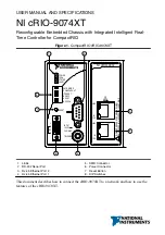
Summary of Contents for NI cRIO-9074XT
Page 1: ...cRIO 9074...


