background image

Power Requirements

Voltage input range

19 V to 30 V

Maximum power input

20 W

Maximum power consumption

20 W

Physical Characteristics

If you need to clean the module, wipe it with a dry towel.

Tip


For two-dimensional drawings and three-dimensional models of the C Series

module and connectors, visit 

ni.com/dimensions

 and search by module number.

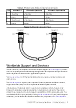
Screw-terminal wiring

Gauge

0.13 mm 

2

 to 2.1 mm

2

 (26 AWG to 14 AWG)

copper conductor wire

Wire strip length

6 mm (0.24 in.) of insulation stripped from the
end

Temperature rating

85 °C

Torque for screw terminals

0.20 N · m to 0.25 N · m (1.8 lb · in. to
2.2 lb · in.)

Wires per screw terminal

One wire per screw terminal

Ferrules

0.25 mm

2

 to 1.5 mm

2

Connector securement

Securement type

Screw flanges provided

Torque for screw flanges

0.3 N · m to 0.4 N · m (2.7 lb · in. to
3.5 lb · in.)

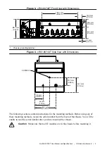
Dimensions (unloaded)

286.4 mm × 88.1 mm × 58.9 mm
(11.3 in. × 3.5 in. × 2.3 in.)

Weight

929 g (32.7 oz)

Safety Voltages

Connect only voltages that are within the following limits:

V terminal to C terminal

35 V maximum, Measurement Category I

Measurement Category I is for measurements performed on circuits not directly connected to
the electrical distribution system referred to as 

MAINS

 voltage. MAINS is a hazardous live

electrical supply system that powers equipment. This category is for measurements of voltages
from specially protected secondary circuits. Such voltage measurements include signal levels,

NI cRIO-9074XT User Manual and Specifications

  | 

© National Instruments

  | 

19

Summary of Contents for NI cRIO-9074XT

Page 1: ...cRIO 9074...

Page 2: ...T SEPARATE CABLES WHEN ENERGIZED IN HAZARDOUS LOCATIONS SAFE MODE CONSOLE OUT IP RESET NO APP USER1 NO FPGA LINK LINK 10 100 10 100 RESET INPUT 19 30 V 20 W MAX TRIGGER V C NC C 1 LEDs 2 RS 232 Serial...

Page 3: ...as been switched off or the area is known to be nonhazardous Caution Do not remove modules unless power has been switched off or the area is known to be nonhazardous Caution Substitution of components...

Page 4: ...d void your authority to operate it under your local regulatory rules Special Conditions for Marine Applications Some products are Lloyd s Register LR Type Approved for marine shipboard applications T...

Page 5: ...tions Caution Your installation must meet the following requirements for space and cabling clearance Allow 25 4 mm 1 in on the top and the bottom of the chassis for air circulation Allow 50 8 mm 2 in...

Page 6: ...in 44 mm 1 73 in 23 7 mm 0 94 in 63 1 mm 2 48 in 44 1 mm 1 74 in The following sections contain instructions for the mounting methods Before using any of these mounting methods record the serial numbe...

Page 7: ...because they are the correct depth and thread for the panel Tighten the screws to a maximum torque of 1 3 N m 11 5 lb in Figure 5 Installing the Panel Mount Accessory on the cRIO 9074XT NI cR IO 9074...

Page 8: ...il Complete the following steps to mount the chassis on a DIN rail 1 Fasten the DIN rail clip to the chassis using a number 2 Phillips screwdriver and two M4 16 screws NI provides these screws with th...

Page 9: ...the mechanical dimensions of C Series I O modules Figure 9 C Series I O Module Front and Side View with Dimensions 88 1 mm 3 47 in 70 7 mm 2 78 in 22 9 mm 0 90 in Complete the following steps to inst...

Page 10: ...hat no I O side power is connected to the I O module If the system is in a nonhazardous location the chassis power can be on when you remove I O modules 2 Squeeze the latches on both sides of the modu...

Page 11: ...to the grounding electrode system of your facility using a method appropriate for the application Caution If you use shielded cabling to connect to a C Series I O module with a plastic connector you m...

Page 12: ...n The Status LED turns off indicating that the POST is complete If the LEDs do not behave in this way when the system powers on refer to the Understanding LED Indications section You can configure the...

Page 13: ...ller either with or without cycling power Connecting Serial Devices to the cRIO 9074XT The cRIO 9074XT has an RS 232 serial port to which you can connect devices such as displays or input devices Use...

Page 14: ...Info Code criosmb Configuring DIP Switches Figure 13 DIP Switches 1 6 5 4 3 2 SAFE MODE CONSOLE OUT IP RESET NO APP USER1 NO FPGA OFF All of the DIP switches are in the OFF position when the chassis...

Page 15: ...Push the NO APP switch to the ON position to prevent a LabVIEW RT startup application from running at startup If you want to permanently disable a LabVIEW RT application from running at startup you m...

Page 16: ...ED to meet the needs of your application Refer to LabVIEW Help for information about programming this LED STATUS LED The STATUS LED is off during normal operation The cRIO 9074XT indicates specific er...

Page 17: ...of your application To define the LED use the RT LEDs VI in LabVIEW For more information about the RT LEDs VI refer to the LabVIEW Help Troubleshooting Network Communication If the cRIO 9074XT cannot...

Page 18: ...unless otherwise noted Caution Do not operate the cRIO 9074XT in a manner not specified in this document Product misuse can result in a hazard You can compromise the safety protection built into the...

Page 19: ...pical input capacitance 2 5 pF Typical resistive strapping 1 k to 3 3 V Memory Nonvolatile 256 MB minimum DRAM 128 MB For information about the life span of the nonvolatile memory and about best pract...

Page 20: ...screw terminal Ferrules 0 25 mm2 to 1 5 mm2 Connector securement Securement type Screw flanges provided Torque for screw flanges 0 3 N m to 0 4 N m 2 7 lb in to 3 5 lb in Dimensions unloaded 286 4 mm...

Page 21: ...equirements of the following electrical equipment safety standards for measurement control and laboratory use IEC 61010 1 EN 61010 1 UL 61010 1 CSA 61010 1 EN 60079 0 2012 EN 60079 15 2010 IEC 60079 0...

Page 22: ...cation column Shock and Vibration To meet these specifications you must panel mount the system Operating vibration Random IEC 60068 2 64 5 grms 10 Hz to 500 Hz Sinusoidal IEC 60068 2 6 5 g 10 Hz to 50...

Page 23: ...Battery Replacement and Disposal Cd Hg Pb Battery Directive This device contains a long life coin cell battery If you need to replace it use the Return Material Authorization RMA process or contact an...

Page 24: ...t ni com services for NI Factory Installation Services repairs extended warranty and other services Visit ni com register to register your NI product Product registration facilitates technical support...

Page 25: ...cts technology refer to the appropriate location Help Patents in your software the patents txt file on your media or the National Instruments Patent Notice at ni com patents You can find information a...

Reviews: