©
National Instruments Corporation
5
Getting Started with the NI EVS-1464RT
•
Mount the NI EVS-1464RT with the heatsink facing upward. If you mount the NI EVS-1464RT on
a wall or other vertical surface, mount the device so that the heat sink fins are vertical.
Refer to the
NI EVS-1464 Series User Manual
for dimensional drawings, additional mounting
information, and detailed device specifications.
Unpack and Verify Components
Remove the NI EVS-1464RT from the package and inspect the system for any sign of damage. Notify
National Instruments if the system appears damaged in any way. Do not use a damaged system.
Hardware Installation
Ensure that the AC input to the external power supply is disconnected before plugging in or unplugging
any connector. Ground the unit to minimize the possibility of static electricity damage.
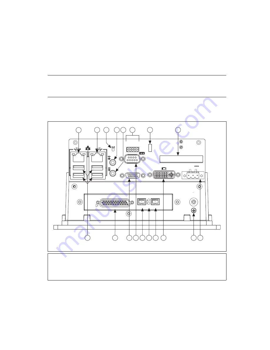
Refer to Figure 1 while completing the following steps to install the NI EVS-1464RT.
Figure 1.
NI EVS-1464RT Connectors
1
Primary Network Connector
2
Secondary Network Connector
3
Reset Switch
4
Audio In Connector
5
Audio Out Connector
6
Safe Mode/IP Reset/No App/
User 1/CF Master/Slave Switches
7
User 2/User 1/HDD/Power LEDs
8
CompactFlash Slot
9
Power Supply Connector
10 Grounding Lug
11 DVI-I Connector
12 IEEE 1394b Bilingual Connector
13 ISO/CAM Power Status LEDs
14 IEEE 1394b Bilingual Connector
15 RS-232 Serial Connector (COM1)
16 MXI Express x1 Connector
17 Digital I/O Connector
18 USB Connectors
RESET
MXIex1
COMPACT FLASH
INPUT
10-20V
90W MAX
USER 2
USER 1
HDD
POWER
CF MS/SL
SAFE MODE
IP
RESET
NO APP
USER 1
DIGITAL I/O
!
IEEE 1
3
94
b
IEEE 1
3
94
b
CAM
I
S
O
1
2
3
7
8
9
11
16
1
8
6
5
17
14 1
3
12
15
10
4


