©
National Instruments Corporation
15
MID-7604/7602 Power Drive User Guide
enabled, the current decreases by 50% when no stepping has occurred for
approximately 500 ms. DIP switch 5 controls current reduction on a
per-axis basis. When this DIP switch is on, current reduction is enabled.
When this DIP switch is off, current reduction is disabled. The factory
default setting is current reduction enabled.
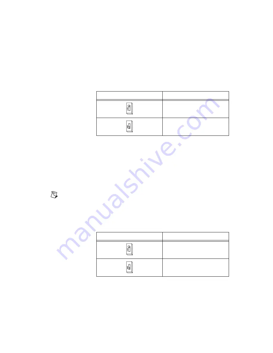
Table 4 shows the available settings for DIP switch 5.
Inhibit Input Polarity Setting
The MID-7604/7602 has a DIP switch that globally sets the polarity for the
inhibit input for all axes. DIP switch 10 on the axis 1 DIP switch bank
controls this setting. Refer to Figures 1 and 3 for the location of this switch.
The factory default setting of DIP switch 10 is active low. If the inhibit
input is active, the axis is inhibited and the yellow status LED (middle row)
and red status LED (top row) illuminates for the axis.
Note
In older versions of the MID-7604/7602, the red status LEDs do not illuminate when
the yellow status LEDs illuminate. This behavior only occurs in newer versions of the
MID-7604/7602.
Table 5 shows the DIP switch setting for the inhibit input polarity selection.
Table 4.
Current Reduction DIP Switch Settings
Switch Setting
Operation
Current reduction enabled
(factory default)
Current reduction disabled
Table 5.
Inhibit Input Polarity DIP Switch Settings
Axis 1 Switch Setting
Operation
Active high
Active low
(factory default)
5
O
N
5
O
N
10
O
N
10
O
N


