
Chapter 2
Installation and Configuration
2-10
ni.com
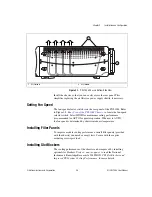
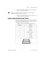
You can use the Inhibit signal (active low) to power off the chassis. To
remotely power off the chassis, connect the Inhibit pin (pin 5) to a Logic
Ground pin (pin 1 or 9). As long as this connection exists, the chassis will
remain off (standby); when you remove this connection, the chassis
turns on.
Note
For the Inhibit signal to control the On/Off (Standby) state of the chassis, the front
power switch must be in the On (recessed) position.
Caution
When connecting digital voltmeter probes to the rear 9-pin D-Sub connector, be
careful not to short the probe leads together. Doing so could damage the power supply.
Caution
Use the rear-panel 9-pin D-Sub connector to check voltages only. Do
not
use the
connector to supply power to external devices, or damage to the chassis may result.
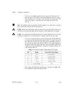
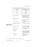
You can use a digital voltmeter to ensure all voltage levels in the PXI-1044
are within the allowable limits. Referring to Table 2-2, connect one lead of
the voltmeter to a supply pin on the remote power monitoring connector
(9-pin D-Sub) on the rear panel. Refer to Table 2-1 for a pinout diagram of
the remote voltage monitoring connector. Connect the reference lead of the
voltmeter to one of the ground pins. Compare each voltage reading to the
values listed in Table 2-2.
If the voltages fall within the specified ranges, the chassis complies with
the CompactPCI voltage-limit specifications.
Table 2-2.
Power Supply Voltages at Voltage Monitoring Connector
Pin
Supply
Acceptable Voltage Range
2
+5 V
4.75 to 5.25 V
4
+3.3 V
3.135 to 3.465 V
6
+12 V
11.4 to 12.6 V
8
–12 V
–12.6 to –11.4 V
1, 9
Logic Ground
0 V