
Index
I-2
ni.com
filler panel installation, 2-3
installing a PXI controller, 2-5
module installation, 2-6, 2-7
injector/ejector handle position
PXI configuration in MAX, 2-11
PXI controller installed in a PXI-1044
rack mounting, 2-4
remote voltage monitoring and inhibiting
setting fan speed, 2-3
site considerations, 2-2
slot blocker installation, 2-3
testing power up, 2-4
unpacking the PXI-1044, 1-1
instrument drivers (NI resources), C-1
interoperability with CompactPCI, 1-5
K
key features, 1-2
kit contents, 1-1
KnowledgeBase, C-1
L
local bus, routing (figure), 1-6, 1-7
M
cleaning
exterior cleaning, 3-2
fan filters, 3-2
interior cleaning, 3-2
resetting the AC mains circuit
service interval, 3-1
static discharge damage (caution), 3-1
N
National Instruments support and
O
P
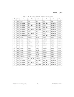
P1 (J1) connector
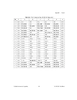
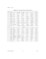
peripheral slot (table), B-6
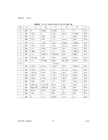
star trigger slot (table), B-4
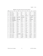
system controller slot (table), B-2
P2 (J2) connector
peripheral slot (table), B-7
star trigger slot (table), B-5
system controller slot (table), B-3
peripheral slots
overview, 1-6
P1 (J1) connector pinouts (table), B-6
P2 (J2) connector pinouts (table), B-7
D-Sub connector (table), 2-9
P1 (J1) connector
peripheral slot (table), B-6
star trigger slot (table), B-4
system controller slot (table), B-2
P2 (J2) connector
peripheral slot (table), B-7
star trigger slot (table), B-5
system controller slot (table), B-3


