
Index
©
National Instruments Corporation
I-3
power supply
connecting to, 2-4
remote voltage monitoring and inhibiting
replacing
configuration, 3-4
connecting safety ground, 3-5
connecting to power source, 3-5
installation, 3-4
removal, 3-4
voltages at voltage monitoring connector
power switch LED indicator, 2-8
power up, testing, 2-4
programming examples (NI resources), C-1
PXI controller, 2-5
installing in a PXI-1044 chassis
PXI_CLK10, 1-8
PXI_CLK10_IN pin, 1-8
PXI-1044
cooling air intake (figure), 2-3
fan speed, setting, 2-3
front view (figure), 1-3
installation.
See
installation,
configuration, and operation
See
maintenance of
PXI-1044
optional equipment, 1-4
rack mounting, 2-4
rack-mount kits, 1-4
rear view of chassis, 1-4
safety ground, connecting, 2-4
PXI-1044 backplane
interoperability with CompactPCI, 1-5
local bus, 1-6
overview, 1-5
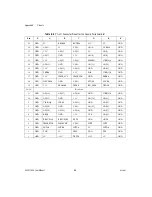
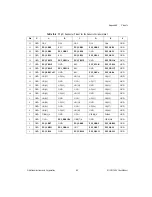
peripheral slots, 1-6
specifications, A-6
star trigger (ST) slot, 1-6
system reference clock, 1-8
trigger bus, 1-8
R
rack mount kit dimensions (figure), A-10
rack mounting, 2-4
rack-mount kits, 1-4
related documentation,
remote voltage monitoring and inhibiting
connector
pinout (table), 2-9
power supply voltages (table), 2-10
S
safety and caution notices, 2-1
safety ground, connecting, 2-4
safety specifications (table), A-4
service interval, 3-1
setting fan speed, 2-3
slot blocker
software (NI resources), C-1
specifications
backplane, A-6
chassis cooling, A-3
dimensions (figure), A-8, A-9
electrical
electromagnetic compatibility, A-4
environmental, A-5
mechanical, A-7
rack mount kit dimensions (figure), A-10
safety, A-4
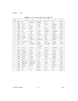
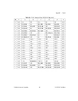
star trigger (ST) slot
description, 1-6
P1 (J1) connector pinouts (table), B-4
P2 (J2) connector pinouts (table), B-5


