Chapter 1
Getting Started
©
National Instruments Corporation
1-3
•
Front-panel LED that can indicate power supply failure
•
10 MHz REF IN and OUT BNC connectors for synchronizing multiple
chassis using PXI_CLK10
•
Programmable PXI trigger routing between PXI bus segments
•
Carrying handle for portability
•
Tilt feet for bench-top applications
•
Rack mountable
Chassis Description
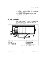
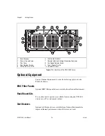
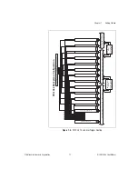
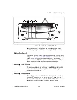
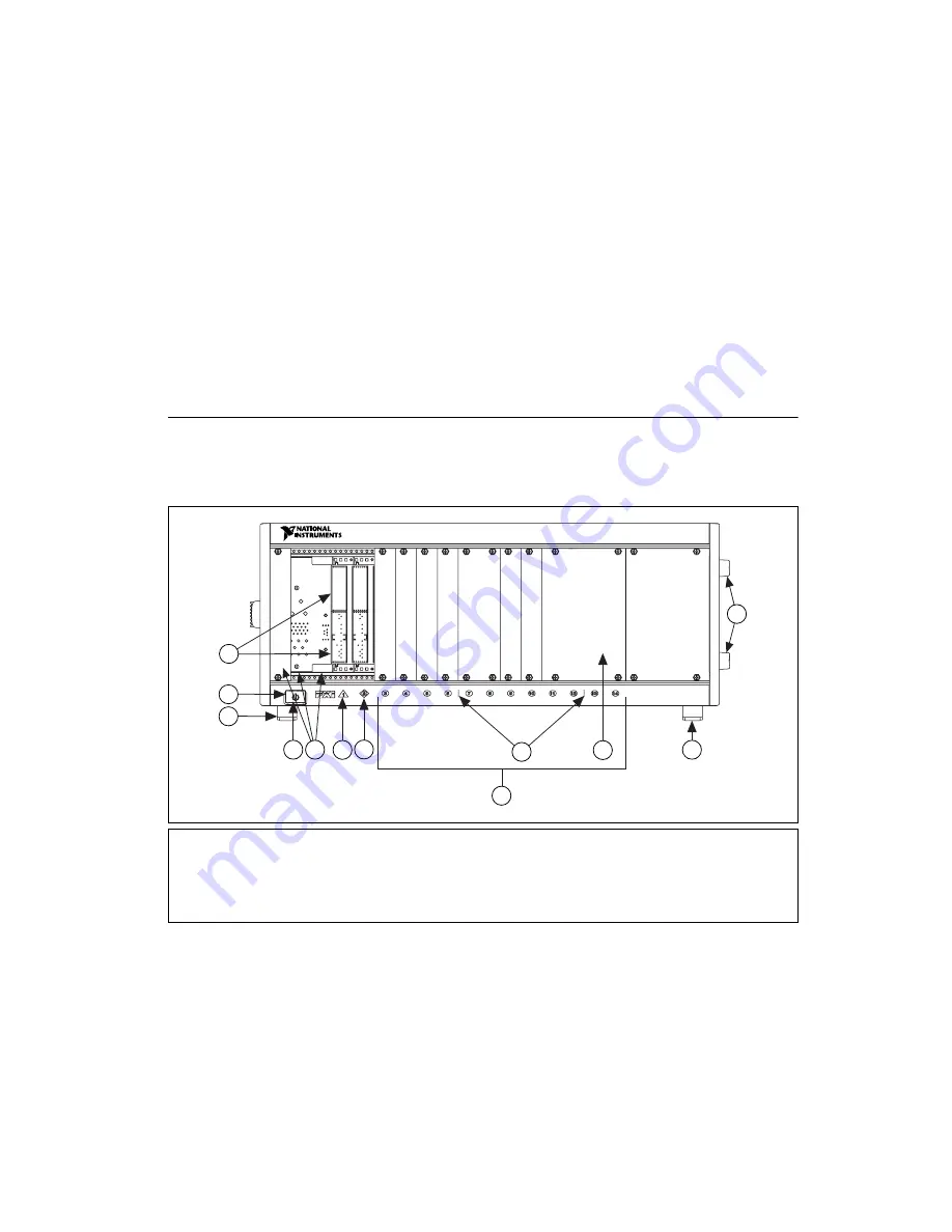
Figures 1-1 and 1-2 show the key features of the PXI-1044 chassis front
and rear panels. Figure 1-1 shows the front view of the PXI-1044.
Figure 1-2 shows the rear view.
Figure 1-1.
Front View of the PXI-1044 Chassis
1
Backplane Connectors (Located in slots 1–14)
2
Removable Feet
3
Filler Panel
4
Generic Peripheral Slots
5
PXI Bus Segment Dividers
6
Star Trigger/Peripheral Slot
7
System Controller Slot
8
Controller Expansion Slots
9
Power Switch LED
10 On/Off (Standby) Power Switch
2
2
10
1
NI PXI-1044
6
7
9
5
3
2
4
8


