Chapter 2
Installation and Configuration
2-2
ni.com
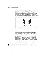
You can configure the SCXI subsystem for one of 32 different addresses so
that you can connect multiple SCXI chassis to the same control source. The
five switches on the front panel of Slot 0 determine the chassis address.
Switches one through five represent the values 1, 2, 4, 8, and 16
respectively, when set to the ON position. When set to the OFF position,
their value is 0. The chassis address is the sum of the switch values.
Figure 2-1 shows examples of both the factory-default setting of the chassis
address 0 and the switch setting for chassis address 19.
Figure 2-1.
Address Setting Examples
Line Voltage Selection and Fuse Values
The voltage selection wheel and fuse should be correct for operation
in your geographical region (the -0
x
extension of the kit part number
corresponds to your geographical region). Check the voltage on the voltage
selection wheel to ensure that you have the correct voltage setting and fuse.
The PXI-1050 chassis can operate with line voltages of 100, 120, 220,
and 240 VAC. The voltage selection wheel in the power entry module
determines the voltage for which the chassis is configured. Identify the
operating voltage by looking at the number on the power entry module
when the selection wheel door is closed. The fuse is a 5 by 20 mm
SLO-BLO type, which has a current rating relative to the operating voltage.
Table 2-1 shows the proper voltage selection and fuse ratings for different
geographical regions.
Caution
For continued protection against fire, replace fuses only with fuses of the same
type and rating.
1
Chassis Default Address = 0
2
Address = 19
3
ON
5
4
3
2
1
5
4
3
2
1
3
3
1
2


