background image

2-8

|

ni.com

Chapter 2

Installation and Configuration

ExpressCard WAKE#

1

—This setting enables or disables an ExpressCard device’s ability 

to wake a soft off system. The default value is 

Disabled

.

PXIe Backplane WAKE#

—This setting enables or disables a PXI Express peripheral 

module’s ability to wake a soft off system. The default value is 

Disabled

.

SMBus ALERT#

—This setting enables or disables a System Management device’s ability 

to wake a soft off system by asserting the ALERT# signal. The default value is 

Disabled

.

ExpressCard Configuration Submenu

Note

This submenu is available on the PXIe-8840 ExpressCard variant only.

Use this submenu to apply alternate settings to the ExpressCard configuration. These settings 
determine how much memory space, I/O space, and PCI bus numbers is pre-allocated for the 
ExpressCard port, allowing non-PCI Express-aware operating systems to support hot-plugging 
ExpressCard devices. Normally, you do not need to modify these settings, as the factory default 
settings provide the most compatible and optimal configuration possible.

ExpressCard Resources

—This setting enables or disables the setting of the 

Reserved 

Buses

Reserved Memory

, and 

Reserved I/O

 settings. The default value for this setting is 

Enabled

. If this setting is disabled, the bus, memory, and I/O options disappear from this 

submenu. Disabling this setting effectively sets 

Reserved Buses

 to

 0

Reserved Memory


to 

0M

, and 

Reserved I/O 

to

 0K

.

Reserved Buses

—This setting determines the number of PCI buses reserved by the BIOS 

for ExpressCard PCI-PCI bridges that may be hot-plugged in the ExpressCard slot. The 
default value for this setting is 

8

 PCI buses.

Reserved Memory

—This setting determines the amount of memory space, in bytes, 

reserved by the BIOS for PCI-PCI bridges that may be hot-plugged in the ExpressCard slot. 
The default value for this setting is 

64M

 bytes of memory.

Reserved I/O

—This setting determines the amount of I/O space, in bytes, reserved by the 

BIOS for PCI-PCI bridges that may be hot-plugged in the ExpressCard slot. The default 
value for this setting is 

4K

 bytes of I/O space.

PCI Configuration Submenu

Use this submenu to apply alternate settings to PCI devices. Normally, you do not need to 
modify these settings, as the factory default settings provide the most compatible and optimal 
configuration possible. 

PCIe Max Payload Size

—This setting determines the maximum payload size of 

PCI Express devices. Valid options are 

Auto

 and 

128 Bytes

. The default value is 

Auto

which allows the BIOS to choose an optimal value based on which devices are present.

1   

Available on the PXIe-8840 ExpressCard variant only.

Summary of Contents for NI PXIe-8840

Page 1: ...PXI Express PXIe 8840 User Manual PXIe 8840 User Manual April 2018 374236B 01...

Page 2: ...email addresses and current events National Instruments Corporate Headquarters 11500 North Mopac Expressway Austin Texas 78759 3504 USA Tel 512 683 0100 For further support information refer to the N...

Page 3: ...TABILITY FITNESS FOR A PARTICULAR PURPOSE TITLE OR NON INFRINGEMENT AND ANY WARRANTIES THAT MAY ARISE FROM USAGE OF TRADE OR COURSE OF DEALING NI DOES NOT WARRANT GUARANTEE OR MAKE ANY REPRESENTATIONS...

Page 4: ...artner Program are business entities independent from NI and have no agency partnership or joint venture relationship with NI Patents For patents covering NI products technology refer to the appropria...

Page 5: ...e encouraged to try to correct the interference by one or more of the following measures Reorient the antenna of the receiver the device suffering interference Relocate the transmitter the device gene...

Page 6: ...SATA Configuration Submenu 2 6 CPU Configuration Submenu 2 6 Video Configuration Submenu 2 7 Power Wake Configuration Submenu 2 7 ExpressCard Configuration Submenu 2 8 PCI Configuration Submenu 2 8 U...

Page 7: ...Recovery 2 21 Installing an OS 2 21 Installing from a USB CD DVD ROM 2 21 ExpressCard 2 21 Installing an ExpressCard 2 22 Removing an ExpressCard 2 22 Chapter 3 I 0 Information Front Panel Connectors...

Page 8: ...PXIe 8840 User Manual National Instruments ix Appendix A Specifications Appendix B NI Services...

Page 9: ...ion from the defaults and using the hardware Related Documentation The following documents contain information you may find helpful as you read this manual PICMG EXP 0 R2 0 CompactPCI Express Specific...

Page 10: ...mplete software compatibility among PCI based systems for example PXI and PCI Express based systems such as PXI Express PXI Express like PXI leverages from the CompactPCI specification to define a rug...

Page 11: ...PC compatible computer in a compact rugged package The PXIe 8840 has an Intel Core i5 4400E processor 2 7 GHz dual core processor all the standard I O and a 250 GB or larger hard drive It also has a...

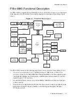
Page 12: ...nterface supporting up to 5 GT s per lane The SO DIMM block consists of one 64 bit DDR3L SDRAM socket that can hold up to 8 GB of memory The processor provides the DisplayPort interface that connects...

Page 13: ...Studio and LabWindows CVI application development environments combine with leading hardware drivers such as NI DAQmx to provide exceptional control of NI hardware Instrument drivers are available at...

Page 14: ...rumentation systems RF applications leverage two drivers NI RFSG and NI RFSA and Dynamic Signal Acquisition is available through NI DAQmx For more information visit ni com modularinstruments You can e...

Page 15: ...ng the PXIe 8840 The power cord grounds the chassis and protects it from electrical damage while you install the module Caution To protect both yourself and the chassis from electrical hazards leave t...

Page 16: ...e as you slowly slide the module into the chassis until the handle catches on the injector ejector rail 5 Raise the injector ejector handle until the module firmly seats into the backplane receptacle...

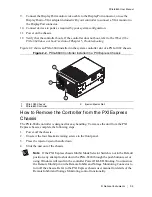
Page 17: ...roller from the PXI Express Chassis The PXIe 8840 controller is designed for easy handling To remove the unit from the PXI Express chassis complete the following steps 1 Power off the chassis 2 Unscre...

Page 18: ...ssage Press DEL to enter setup appears press the Delete key The setup program loads after a short delay The Main menu is displayed when you first enter the BIOS setup program Use the following keys to...

Page 19: ...ge these values System Time This setting controls the time of day which is stored in a battery backed real time clock Most operating systems also include a way to change this setting Use and in conjun...

Page 20: ...de so that non compatible OSes function correctly The default value is AHCI Internal Drive SATA This item displays the onboard SATA drive detected in the system CPU Configuration Submenu Use this subm...

Page 21: ...adjacent cache line prefetching can increase system performance for some applications but can cause control algorithms to behave less deterministically Video Configuration Submenu Use this submenu to...

Page 22: ...for this setting is Enabled If this setting is disabled the bus memory and I O options disappear from this submenu Disabling this setting effectively sets Reserved Buses to 0 Reserved Memory to 0M and...

Page 23: ...pecifies the maximum time a device takes before it properly reports itself to the host controller When set to Auto a root port is granted 100 ms and for a hub port the delay value is taken from the hu...

Page 24: ...startup The default is Use Switch Setting Note By default the target automatically attempts to connect to the network using DHCP If the target is unable to initiate a DHCP connection the target conne...

Page 25: ...by Boot Option 2 and Boot Option 3 If multiple boot devices are not present the BIOS setup utility does not display all of these configuration options To select a boot device press Enter on the desire...

Page 26: ...t Option Priorities list Optionally each device can also be Disabled if the device should never be used as a boot device Floppy Drive BBS Priorities Submenu Boot Option 1 Boot Option 2 Boot Option 3 T...

Page 27: ...tinues to be active Restore Factory Defaults This option restores all BIOS settings to the factory default This option is useful if the controller exhibits unpredictable behavior due to an incorrect o...

Page 28: ...troller and replace the hard drive Memory Diagnostic Utility The memory diagnostic utility is started immediately after the user presses a key to exit the hard drive diagnostic utility The user may ab...

Page 29: ...xpress embedded controller setup to run LabVIEW Real Time In this section you will configure the boot mode of the controller verify or change IP settings and install LabVIEW Real Time software Complet...

Page 30: ...ntry to access the Network Settings tab in the right pane view 4 Optional Enter a name for the RT target in the Name text box 5 Optional Set the network configuration options of the RT target in the I...

Page 31: ...boot LabVIEW RT into safe mode to reconfigure TCP IP settings and to download or update software from a host computer This switch overrides the behavior of Switch 1 Booting the controller into safe m...

Page 32: ...erals The directory structure under the images directory is logically organized into several levels In the images directory are drivers and NIDRIVERS directories The drivers directory contains driver...

Page 33: ...out routing and reserving PXI Express triggers refer to KnowledgeBase 3TJDOND8 Using PXI Timing and Triggering Functionality at ni com support The configuration steps for single or multiple chassis sy...

Page 34: ...ts offers the following SO DIMMs for use with the PXIe 8840 controller 1600 MHz DDR3L PC3 12800 4 GB 512 MB 64 1 18 in max NI part number 782341 4096 1600 MHz DDR3L PC3 12800 8 GB 1024 MB 64 1 18 in m...

Page 35: ...DVD you can use the included OS re installation DVD with an external USB CD DVD ROM drive Boot the PXI Express controller using the OS re installation DVD to recover the OS You also may need to reinst...

Page 36: ...chanism If you insert the card and it is ejected re insert the card until it is seated If you encounter too much resistance do not force the card Check the card orientation and try again The PXIe 8840...

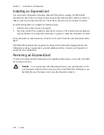
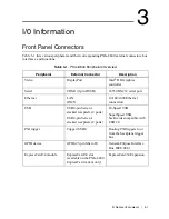
Page 37: ...COM1 9 pin DSUB 16550 RS 232 serial port Ethernet LAN RJ45 10 100 1000 Ethernet connection USB USB 4 pin Series A stacked receptacle 4 ports USB 9 pin Series A stacked receptacle 2 ports Hi Speed USB...

Page 38: ...1 573 in 39 95 mm 2 345 in 59 56 mm 3 087 in 78 41 mm 3 554 in 90 27 mm 4 393 in 111 58 mm 0 000 in 0 00 mm 1 948 in 49 47 mm 3 289 in 83 54 mm 3 750 in 95 25 mm 1 185 in 30 10 mm 2 814 in 71 48 mm 1...

Page 39: ...Table 3 2 lists and describes the DisplayPort connector signals Figure 3 2 DisplayPort Connector Location and Pinout Table 3 2 DisplayPort Connector Signals Pin Signal Name 1 ML_Lane0 p 2 GND 3 ML_La...

Page 40: ...XIe 8840 Table 3 3 lists and describes the COM1 connector signal Figure 3 3 COM1 Connector Location and Pinout 13 CONFIG1 14 CONFIG2 15 AUX CH p 16 GND 17 AUX CH n 18 Hot Plug Detect 19 Return 20 DP_P...

Page 41: ...als Pin Signal Name Signal Description 1 DCD Data Carrier Detect 2 RXD Receive Data 3 TXD Transmit Data 4 DTR Data Terminal Ready 5 GND Ground 6 DSR Data Set Ready 7 RTS Ready to Send 8 CTS Clear to S...

Page 42: ...onnector LED states Note The Wake On LAN feature is only supported by Ethernet Port 1 Figure 3 4 Ethernet Connector Location and Pinout Note The Ethernet controller can perform an automatic crossover...

Page 43: ...dition Top Green Off LAN link is not established On steady state LAN link is established On brighter and pulsing The controller is communicating with another computer on the LAN Bottom Unlit Off 10 Mb...

Page 44: ...the USB 2 0 connector signals Table 3 7 lists and describes the USB 3 0 connector signals Figure 3 5 USB Connector Location and Pinout Table 3 6 USB 2 0 Connector Signals Pin Signal Name Signal Descri...

Page 45: ...40 User Manual 5 StdA_SSRX USB Data Receive 6 StdA_SSRX USB Data Receive 7 GND_DRAIN Ground 8 StdA_SSTX USB Data Transmit 9 StdA_SSTX USB Data Transmit Table 3 7 USB 3 0 Connector Signals Continued Pi...

Page 46: ...r location on the PXIe 8840 Table 3 8 lists and describes the trigger connector signals Note Refer to PXI Express Trigger Connectivity in Chapter 2 Installation and Configuration for more information...

Page 47: ...provides a GPIB mating connector part number 183285 0R2 Figure 3 7 GPIB Connector Location and Pinout Table 3 9 GPIB Connector Signals Pin Signal Name Signal Description 1 DIO1 Data Bit 1 2 DIO2 Data...

Page 48: ...assis ground 13 DIO5 Data Bit 5 14 DIO6 Data Bit 6 15 DIO7 Data Bit 7 16 DIO8 Data Bit 8 17 REN Remote Enable 18 to 25 GND Logic Ground Note The pound symbol indicates an active low signal Table 3 9 G...

Page 49: ...uts for the ExpressCard 34 slot on the PXIe 8840 Table 3 10 lists and describes the ExpressCard connector signals Figure 3 8 ExpressCard 34 Slot Location and Pinout Table 3 10 ExpressCard Connector Si...

Page 50: ...17 CPPE PE Presence 18 REFCLK Reference Clock 19 REFCLK Reference Clock 20 GND Ground 21 PERn0 PE Data Receive 22 PERp0 PE Data Receive 23 GND Ground 24 PETn0 PE Data Transmit 25 PETp0 PE Data Transmi...

Page 51: ...ithin regulation limits Green BLINKING One of the onboard power supplies is operating outside of the normal limits or the system power supply is out of regulation OFF The controller is powered off Red...

Page 52: ...sconnect power Note The Wake On LAN feature is only supported by Ethernet Port 1 How do I check the configuration of the memory hard drive time date and so on You can view these parameters in the BIOS...

Page 53: ...set the order for the devices listed within the device type To boot from a different device without changing the boot order in the BIOS press F10 continuously while booting After the BIOS completes th...

Page 54: ...ort is installed by default when your controller is first shipped from the factory To change the default installed driver complete the following steps 1 Download the latest GPIB driver from ni com dow...

Page 55: ...3 12800 8 GB 1024 MB 64 1 18 in max NI part number 783001 8192 Note National Instruments has tested and verified that the DDR3L SO DIMMs we sell work with the PXIe 8840 We recommend you purchase your...

Page 56: ...test software drivers The latest National Instruments software is available from ni com downloads PXI Express Configuration How do I use the SMB trigger on the front panel For details refer to the PXI...

Page 57: ...truments technical support What has changed about the system Did you recently move the system Was there electrical storm activity Did you recently add a new module memory chip or piece of software Ref...

Page 58: ...s not in my chassis The most common cause of this is a damaged module Try the module in a different chassis or with a different controller Also remove any external cables or terminal blocks connected...

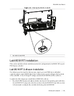
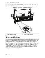
Page 59: ...National Instruments 5 3 PXIe 8840 User Manual Figure 5 1 Clearing the CMOS Contents 1 Push Button Switch S1 1...

Page 60: ...l ATA minimum Ethernet Two 10 100 1000 BaseT ports PXI Express 4 Link Configuration x4 x4 x4 x4 PXI Express 2 Link Configuration x8 x8 GPIB IEEE 488 Controller Yes Serial Ports RS 232 Yes 1 Parallel P...

Page 61: ...re that the device is completely dry and free from contaminants before returning it to service Operating Environment Ambient temperature range 5 to 50 C Tested in accordance with IEC 60068 2 1 and IEC...

Page 62: ...Tested in accordance with IEC 60068 2 56 Shock and Vibration Operating shock 30 g peak half sine 11 ms pulse Tested in accordance with IEC 60068 2 27 Meets MIL PRF 28800F Class 2 limits Random vibrat...

Page 63: ...ic or medical equipment that does not intentionally generate radio frequency energy for the treatment of material or inspection analysis purposes Note For EMC declarations and certifications and addit...

Page 64: ...ts WEEE initiatives and compliance with WEEE Directive 2002 96 EC on Waste and Electronic Equipment visit ni com environment weee Battery Replacement and Disposal Battery Directive This device contain...

Page 65: ...y your systems accuracy and reliability requirements and provides warranty sparing and calibration services to help you maintain accuracy and minimize downtime over the life of your system Visit ni co...

Page 66: ...tions Engineers make sure every question submitted online receives an answer Software Support Service Membership The Standard Service Program SSP is a renewable one year subscription included with alm...

Reviews: