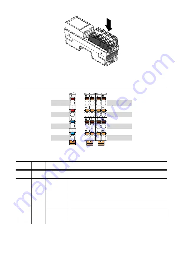
REM-11115 Pinout
AO0 to AO3
AO0 to AO3
COM
COM
00
10
20
30
01
11
21
31
02
12
22
32
03
13
23
33
24 VDC
24 VDC
GND
GND
a1
a2
b2
b1
Table 2. REM-11115 Signal Descriptions
Signal
Color
Description
a1, a2
Red
24 VDC (U
A
) Analog module supply (internally jumpered)
b1, b2
Blue
GND
Reference potential of the supply voltage (internally
jumpered)
00 to 03 Orange AO0 to AO3 Voltage connection for channel 0 to 3
10 to 13
AO0 to AO3 Current connection for channel 0 to 3
20 to 23
COM
Reference potential for all channels
30 to 33
COM
Reference potential for all channels
REM-11115 Getting Started Guide
|
© National Instruments
|
7


