NI PXIe-4340 and TB-4340 User Guide and Terminal Block Specifications
|
© National Instruments
|
7
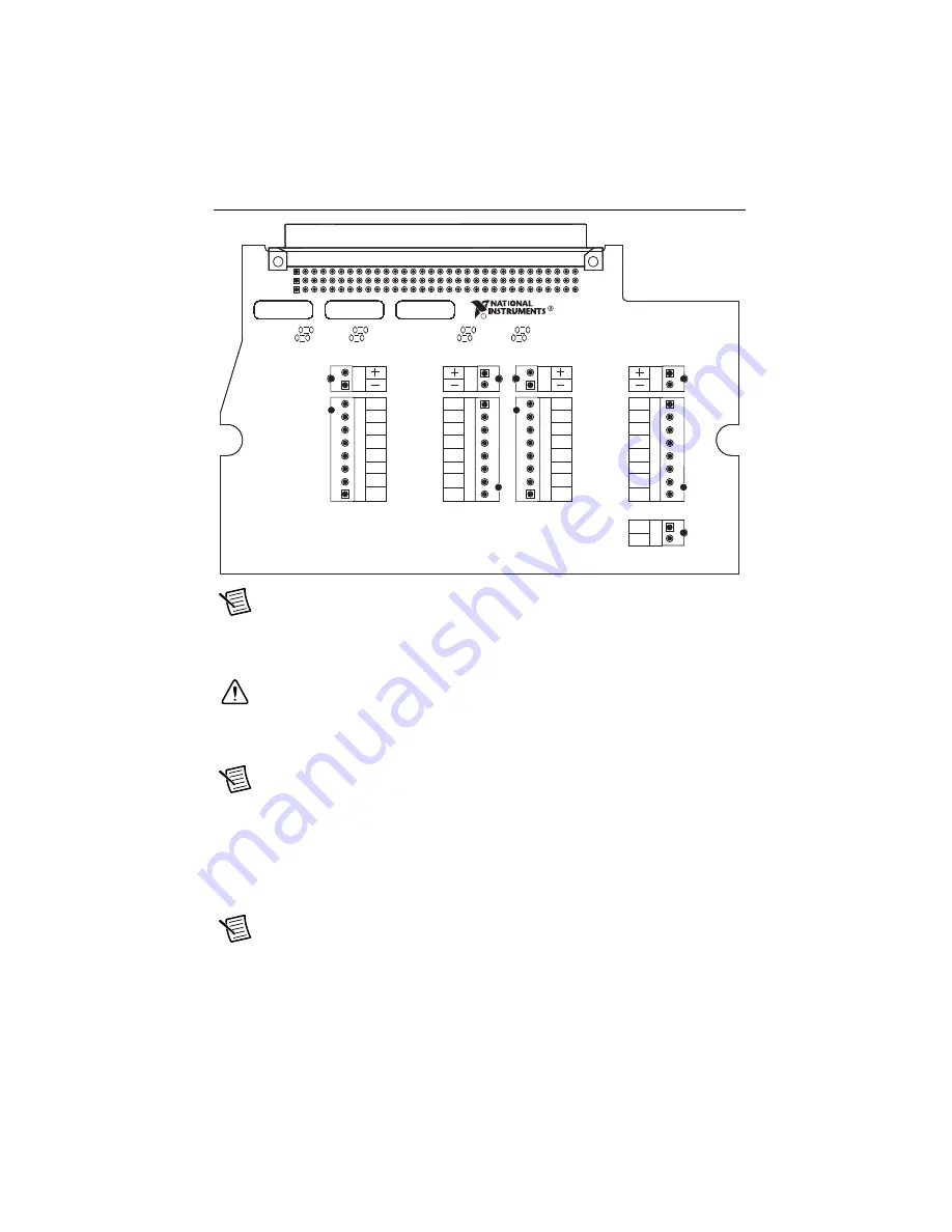
Figure 4.
TB-4340 Circuit Board Parts Locator Diagram
Note
Refer to the
NI PXIe-4340 User Manual
for wiring diagrams showing how to
connect sensors to the TB-4340.
6.
Tighten the terminal screws to a torque of 0.2 to 0.25 N · m (1.77 to 2.21 lb · in.).
Caution
Any wires connected to the ground must be sufficiently insulated from
high voltage.
7.
Use the ground lugs to attach a shield wire to the ground.
Note
Refer to the
NI PXIe-4340 User Manual
for details about shielding the
signals.
8.
Reinstall the strain-relief bar and tighten the strain-relief screws.
9.
Use tie wraps to connect the shielded signal wires to the tie-wrap holes for additional strain
relief when necessary.
10. Reinstall the top cover and tighten the captive top cover screws.
Note
For information about sensors, go to
.
C1
B1
A1
COPYRIGHT 2015
S/N
159026B-01L
NI TB-4340
EX+
EX–
RS+
RS–
AI+
AI–
CT
AIGND
CHANNEL 0
EXITATION
VERIFICATION
EX+
EX–
RS+
RS–
AI+
AI–
CT
AIGND
CHANNEL 2
EXITATION
VERIFICATION
EX+
EX–
RS+
RS–
AI+
AI–
CT
AIGND
CHANNEL 1
EX+
EX–
RS+
RS–
AI+
AI–
CT
AIGND
CHANNEL 3
PFIO
DGND
R11
R10
R13
R12
R15
R14
R17
R16
C


