NI PXIe-4340 and TB-4340 User Guide and Terminal Block Specifications
|
© National Instruments
|
5
8.
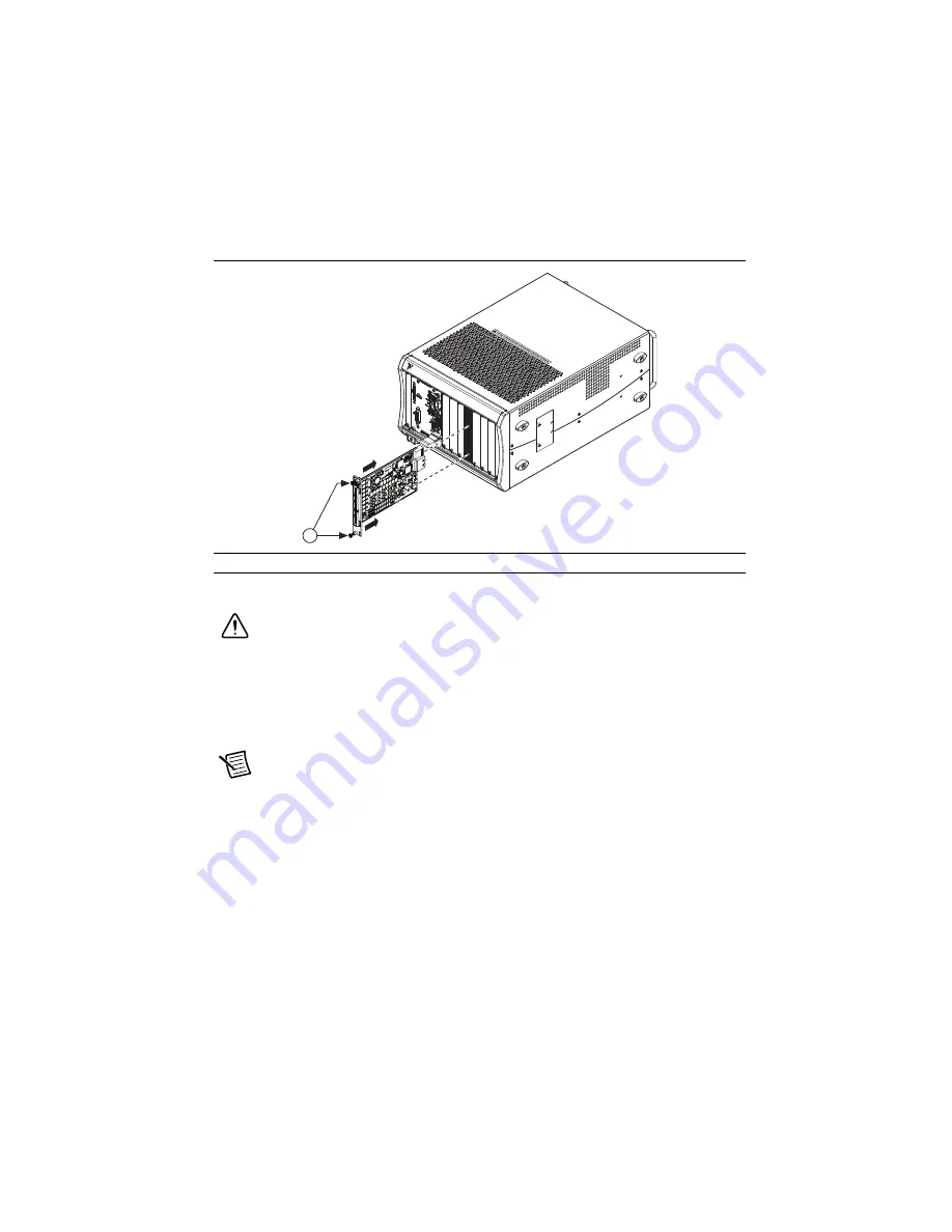
Secure the module to the chassis using the front-panel captive screws, shown in Figure 2.
Tighten the screws to 0.31 N
·
m (2.7 lb · in.).
Figure 2.
Installing PXIe-4340
Modules
Connect the Signals
Caution
To ensure the specified EMC performance, operate this product only with
shielded cables and shielded accessories. Use only twisted, shielded pair cables for
channel connections. Refer to the
NI PXIe-4340 User Manual
for specific guidance
on terminating cable shields.
To connect signals to the terminal block, refer to Figures 3 and 4 while completing the following
steps:
Note
You can find the pinout names and locations in Measurement & Automation
Explorer (MAX) at any time by right-clicking the device name under
Devices and
Interfaces
and selecting
Device Pinouts
.
1.
Loosen the captive top cover screws and remove the top cover.
2.
Loosen the strain-relief screws and remove the strain-relief bar.
3.
Prepare the shielded signal wire by stripping the insulation no more than 7 mm (0.28 in.).
4.
Run the shielded signal wires through the strain-relief opening.
1
Captive Screws
NI
PX
Ie-1062Q
CO
OLING
CL
EAR
ANCE
AND
FAN
FILT
ER
MA
INT
ENA
NC
E RE
QU
IRE
D.
S
EE MA
NU
AL.
1
NAT
ION
AL
INSTR
UM
ENT
S


