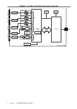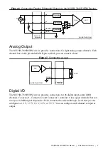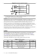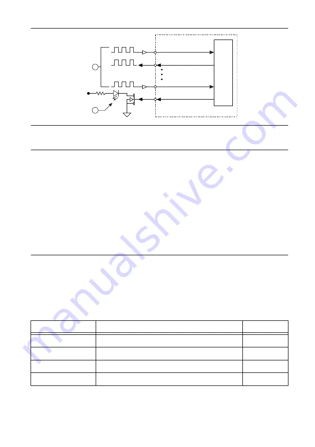
Figure 8. Connecting to the DIO Channels
NI USB-7845R OEM
Power
FPGA
Connector X/ DIO0
Connector X/ DIO1
Connector X/ DIO14
Connector X/ DIO15
1
2
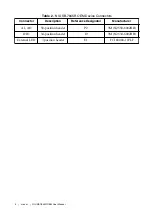
1. Low-speed signal frequencies up to 10 MHz with logic levels configured as 1.2 V, 1.5 V, 1.8 V, 2.5 V, or
3.3 V. Connectors 1 and 2 share the same voltage settings.
2. LED.
The DIO channels connect to the FPGA through buffers, which have overvoltage and
undervoltage protection as well as over current protection. Refer to the
NI USB-7845R OEM
Device Specifications
for more information about the maximum voltage and current.
When the system powers on, the DIO channels are set as input low with pull-down resistors.
To set another power-on state, you can configure the NI USB-7845R OEM device to load a VI
when the system powers on. The VI can then set the DIO lines to any power-on state.
National Instruments recommends performing signal integrity measurements to test the effect
of signal routing with the cable and connection accessory for your application.
LEDs
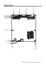
If you are putting the NI USB-7845R OEM device in an enclosure, you can either seat the
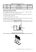
optional lightpipes on the device or attach external LEDs, as described in the
section. When the lightpipes are attached, the top row is Error, USB Ready,
and POWER LEDs, and the bottom row has the User LEDs.
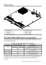
The NI USB-7845R OEM device has six LEDs which reflect the device state.
Table 3. LED Descriptions
LED
Description
Location
POWER
Solid blue when the power is on
6
USB READY
Solid blue when the USB is ready
3
ERROR
Solid red for error cases
2
USER1
Blue, user-defined
1
10
|
ni.com
|
NI USB-7845
R
OEM User Manual


