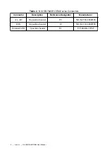
Table 3. LED Descriptions (Continued)
LED
Description
Location
USER2
Blue, user-defined
4
USER3
Blue, user-defined
5
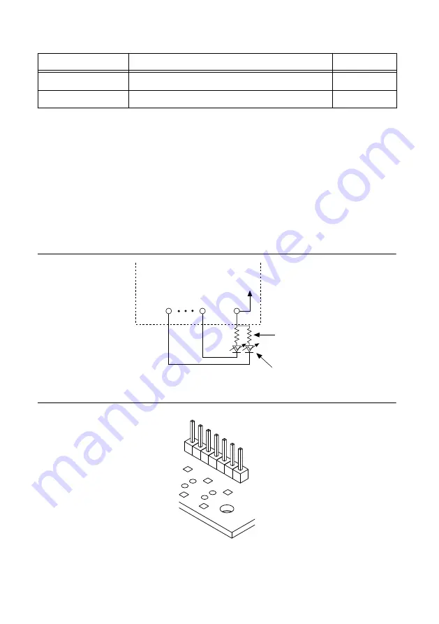
Attaching External LEDs
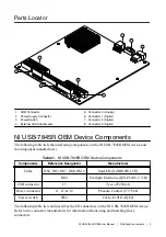
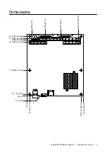
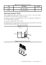
Seven connectors on the device in the E1 part —1, 2, 3, 4, 5, 6, and 7— allow you to connect
an external LED circuit to the device, as shown in Figure 10.
For example, to connect an external USB READY LED, use 7 as the positive connection (+5
V) and 3 and the negative connection.
To connect the remaining LEDs, refer to Table 3.
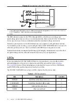
National Instruments recommends that you limit the current to 10 mA per LED. You can limit
this current by using external resistors, as shown in Figure 9.
Figure 9. External LEDs
External
LED
+5 V
OEM (On-Board)
7
6
1
External
Resistor
Figure 10. Attaching External LEDs
1
2
3
4
5
6
7
NI USB-7845
R
OEM User Manual
|
© National Instruments
|
11


