Power Switch
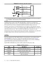
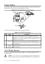
Use the power switch to power the NI USB-7845R OEM device on and off. The following
figure shows the pins on the power switch and power circuitry.
Figure 11. Power Switch (Shown in the On Position)
VDC Out
100 k
Ω
to Ground
VDC In
Switch
1
2
3
NC
NC
SW2
SW2
3
Power to
Device
J8
Power
Connector
1
2
1
2
Connector
J8
1
2
F1
ON
ON
100 k
Ω
100 k
Ω
The following table lists the pin locations and signal descriptions.
Table 4. Power Switch Pin Descriptions
Pin
Signal
Description
1
VDC In
Connects to VDC through a non-user replaceable fuse (reference
designator F1). The VDC is the voltage provided by the power supply
through pin 2 of the power connector (reference designator J8) and
must be 9 V to 30 V, 20 W.
2
VDC Out
Provides power to the circuitry on the NI USB-7845R OEM device.
When the switch is in the on position, the VDC power supply from pin
1 is routed to pin 2.
3
100 kΩ to
Ground
Connects pin 2 to ground through a 100 kΩ resistor when the switch is
in the off position.
+5 V Power Source
Use the +5 V terminals on the I/O connector 5 V referenced to DGND to power
external circuitry.
Caution
Never connect the +5 V power terminals to analog or digital ground or
any other voltage source on the NI USB-7845R OEM device or any other device.
12
|
ni.com
|
NI USB-7845
R
OEM User Manual


