background image

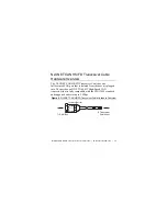
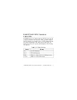
NI-XNET CAN HS/FD Transceiver Cable Instructions

|

© National Instruments

|

23

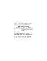
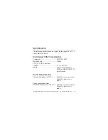
Canada (C-UL) ................................. Class I, Division 2, 

Groups A, B, C, D, T4;
Class I, Zone 2, 
Ex nA IIC T4

Europe (DEMKO) ............................ Ex nA IIC T4 Gc

Environmental

Refer to the installation instructions for the host you are using for 
more information about meeting these specifications.
Operating temperature
(IEC 60068-2-1, IEC 60068-2-2) ..... -40

1

 to 70 °C

Storage temperature
(IEC 60068-2-1, IEC 60068-2-2) ..... -40

1

 to 85 °C

Ingress protection.............................. IP 40
Operating humidity
(IEC 60068-2-56).............................. 10 to 90% RH, 

noncondensing

1  

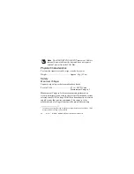
Similar to other standard PVC cables, this product’s cable becomes less ductile at 
low temperatures. Preroute and secure the cable while flexible to avoid premature 
failure.

Summary of Contents for NI-XNET CAN HS/FD

Page 1: ...OPERATING INSTRUCTIONS NI XNET CAN HS FD Transceiver Cable ...

Page 2: ...om downloads Note The safety guidelines and specifications in this document are specific to the NI XNET CAN HS FD Transceiver Cable The other components in your system may not meet the same safety ratings and specifications Refer to the documentation for each component in your system to determine the safety ratings and specifications for the entire system Safety Guidelines Operate the NI XNET CAN ...

Page 3: ...ents for repair Safety Guidelines for Hazardous Locations The NI XNET CAN HS FD Transceiver Cable is suitable for use in Class I Division 2 Groups A B C D T4 hazardous locations Class I Zone 2 AEx nA IIC T4 and Ex nA IIC T4 hazardous locations and nonhazardous locations only Follow these guidelines if you are installing the NI XNET CAN HS FD Transceiver Cable in a potentially explosive environment...

Page 4: ...t IP 54 as defined by IEC 60529 and EN 60529 Caution For Division 2 and Zone 2 applications install a protection device between the CAN bus and the NI XNET CAN HS FD Transceiver Cable CAN pins The device must prevent the CAN Port to COM voltage from exceeding 55 V if there is a transient overvoltage condition Special Conditions for Safe Use in Europe This equipment has been evaluated as Ex nA IIC ...

Page 5: ...onment of not more than Pollution Degree 2 Caution The enclosure must have a door or cover accessible only by the use of a tool Mounting the NI XNET CAN HS FD Transceiver Cable Caution The NI XNET CAN HS FD Transceiver Cable is a thermally active device that dissipates heat Refer to the user manual of the host this device directly connects to for specific information regarding thermal management N...

Page 6: ...ceiver Cable host port Figure 1 NI XNET CAN HS FD Transceiver Cable Connections The NI XNET CAN HS FD Transceiver Cable has one 9 pin male D Sub connector that provides connections to a CAN bus The NI XNET CAN HS FD Transceiver Cable has pins for CAN_H and CAN_L to which you connect the CAN bus signals Connect these signals using twisted pair cable The port has two common pins COM that are interna...

Page 7: ... to the COM signals The NI XNET CAN HS FD Transceiver Cable gets power from the XNET host port No external power from the CAN bus is required Note The NI XNET CAN HS FD Transceiver Cable is internally powered but LIN and some other cables may require external power when the bus standard requires it The NI XNET CAN HS FD Transceiver Cable pinout is listed in Table 1 The NI XNET CAN HS FD Transceive...

Page 8: ...PI call If you choose to use external termination Table 3 lists recommended termination resistor values Table 1 Pin Assignments for the NI XNET CAN HS FD Transceiver Cable Connector Pin Signal 1 No Connection NC 2 CAN_L 3 COM 4 NC 5 NC 6 COM 7 CAN_H 8 NC 9 NC 6 7 8 9 1 2 3 4 5 ...

Page 9: ...wn as a stub The pair of signal wires CAN_H and CAN_L constitutes a transmission line If the transmission line is not terminated each signal change on the bus causes reflections that may cause communication errors Because the CAN bus is bidirectional both ends of the cable must be terminated However this requirement does not mean that every node on the bus should have a termination resistor only t...

Page 10: ...implified diagram of a CAN bus with multiple CAN nodes and proper termination resistor Rt locations Figure 2 CAN Bus Topology and Termination Resistor Locations CAN Node CAN Node CAN Node Rt Rt CAN Node CAN_H CAN_L CAN_H CAN_L CAN_H CAN_L CAN_H CAN_L Bus Cable Length Stub Length ...

Page 11: ...S FD Transceiver Cable port to any location on a CAN bus Figure 3 shows one example of connecting the NI XNET CAN HS FD Transceiver Cable directly to one CAN node Figure 3 Connecting the NI XNET CAN HS FD Transceiver Cable to a CAN Device NI CAN HS Transceiver Cable Port CAN Device Rt CAN Cable With Optional Shield SHLD CAN_H CAN_L Vsup COM Rt SHLD CAN_H CAN_L Vsup COM ...

Page 12: ...t in a system Cable Specifications Cables should meet the physical medium requirements specified in ISO 11898 shown in Table 2 Belden cable 3084A meets all these requirements and should be suitable for most applications Table 2 ISO 11898 Specifications for Characteristics of a CAN_H and CAN_L Pair of Wires Characteristic Value Impedance 95 Ω min 120 Ω nominal 140 Ω max Length related resistance 70...

Page 13: ...e 3 Cable Lengths The cabling characteristics and desired bit transmission rates affect the allowable cable length You can find detailed cable length recommendations in the ISO 11898 CiA DS 102 and DeviceNet specifications ISO 11898 specifies 40 m total cable length with a maximum stub length of 0 3 m for a bit rate of 1 Mb s The ISO 11898 specification says that significantly longer cable lengths...

Page 14: ...he electrical characteristics of the nodes on the network If all nodes meet the ISO 11898 requirements you can connect at least 30 nodes to the bus You can connect higher numbers of nodes if the nodes electrical characteristics do not degrade signal quality below ISO 11898 signal level specifications The NI XNET CAN HS FD Transceiver Cable electrical characteristics allow at least 110 CAN ports on...

Page 15: ...Cable has one full featured CAN port that is isolated from the host it is plugged into The port has an NXP TJA1043T High Speed CAN transceiver that is fully compatible with the ISO 11898 standard and supports baud rates up to 1 Mbps Figure 4 NI XNET CAN HS FD Transceiver Cable Hardware Overview Transceiver Isolation Barrier To CAN Bus To Transceiver Cable Host ...

Page 16: ...le to a host device push the connector assembly into the host receptacle until the internal latch snaps into position The latch emits an audible click when engaged To remove the NI XNET CAN HS FD Transceiver Cable push the lock ejector forward to disengage the latch and simultaneously pull the NI XNET CAN HS FD Transceiver Cable as shown in Figure 5 Figure 5 Inserting and Removing the NI XNET Tran...

Page 17: ...marily indicates whether the hardware is currently in use LED 2 primarily indicates the activity information of the connected bus Each LED can display two colors red or green which display in the following four patterns Table 4 LED Pattern Definitions Pattern Meaning Off No LED illumination Solid LED fully illuminated Blink Blinks at a constant rate of several times per second Activity Blinks in a...

Page 18: ...sion on hardware port is properly powered and hardware is not communicating Solid green Off Hardware is communicating and controller is in Error Active state Solid green Activity green returns to idle off one second after last TX or RX Hardware is communicating and controller is in Error Passive state Solid green Activity red returns to idle off one second after last TX or RX Hardware is running a...

Page 19: ... Speed CAN Characteristics Transceiver NXP TJA1043T Max baud rate 1 Mbps CAN_H CAN_L bus lines voltage 27 to 40 VDC MTBF Contact NI for Bellcore MTBF or MIL HDBK 217F specifications Power Requirements Thermal dissipation at 70 C 550 mW max active mode 440 mW typical active mode Power consumption from NI XNET Transceiver Cable host 550 mW max active mode 440 mW typical active mode ...

Page 20: ...nect only voltages that are within these limits Port to COM 27 to 40 VDC max Measurement Category I Measurement Category I is for measurements performed on circuits not directly connected to the electrical distribution system referred to as MAINS voltage MAINS is a hazardous live electrical supply system that powers equipment This category is for measurements of voltages from specially protected s...

Page 21: ...ithin Measurement Categories II III or IV Note Measurement Categories CAT I and CAT O Other are equivalent These test and measurement circuits are not intended for direct connection to the MAINs building installations of Measurement Categories CAT II CAT III and CAT IV Isolation Voltage Port to earth ground Continuous 60 VDC Measurement Category I Note The NI XNET CAN HS FD Transceiver Cable COM s...

Page 22: ...laboratory use IEC 61010 1 EN 61010 1 UL 61010 1 CSA 61010 1 EN 60079 0 2012 EN 60079 15 2010 IEC 60079 0 Ed 6 IEC 60079 15 Ed 4 UL 60079 0 Ed 5 UL 60079 15 Ed 3 CSA 60079 0 2011 CSA 60079 15 2012 Note For UL and other safety certifications refer to the product label or the Online Product Certification section Hazardous Locations U S UL Class I Division 2 Groups A B C D T4 Class I Zone 2 AEx nA II...

Page 23: ...ou are using for more information about meeting these specifications Operating temperature IEC 60068 2 1 IEC 60068 2 2 401 to 70 C Storage temperature IEC 60068 2 1 IEC 60068 2 2 401 to 85 C Ingress protection IP 40 Operating humidity IEC 60068 2 56 10 to 90 RH noncondensing 1 Similar to other standard PVC cables this product s cable becomes less ductile at low temperatures Preroute and secure the...

Page 24: ...ibration To meet these specifications you must securely mount your transceiver cable and ensure all cables and connectors have proper strain relief Operating vibration random IEC 60068 2 64 5 grms 10 to 500 Hz Operating shock IEC 60068 2 27 30 g 11 ms half sine 50 g 3 ms half sine 18 shocks at 6 orientations 1 60 V CAT I 1000 V Withstand up to 3000 m 60 V CAT I 860 V Withstand from 3001 to 5000 m ...

Page 25: ... equipment for measurement control and laboratory use EN 61326 IEC 61326 Class A emissions Basic immunity EN 55011 CISPR 11 Group 1 Class A emissions AS NZS CISPR 11 Group 1 Class A emissions FCC 47 CFR Part 15B Class A emissions ICES 001 Class A emissions Note For the standards applied to assess the EMC of this product refer to the Online Product Certification section Note For EMC compliance oper...

Page 26: ...efer to the product Declaration of Conformity DoC for additional regulatory compliance information To obtain product certifications and the DoC for this product visit ni com certification search by model number or product line and click the appropriate link in the Certification column Environmental Management NI is committed to designing and manufacturing products in an environmentally responsible...

Page 27: ...trical and Electronic Equipment WEEE EU Customers At the end of the product life cycle all products must be sent to a WEEE recycling center For more information about WEEE recycling centers National Instruments WEEE initiatives and compliance with WEEE Directive 2002 96 EC on Waste and Electronic Equipment visit ni com environment weee ᄤֵᙃѻક ᶧ ࠊㅵ ࡲ Ё RoHS Ё ᅶ National Instruments ヺড়Ё ᄤֵᙃ ѻકЁ䰤ࠊՓ ᶤѯ...

Page 28: ...er services Visit ni com register to register your National Instruments product Product registration facilitates technical support and ensures that you receive important information updates from NI A Declaration of Conformity DoC is our claim of compliance with the Council of the European Communities using the manufacturer s declaration of conformity This system affords the user protection for ele...

Page 29: ... also has offices located around the world For telephone support in the United States create your service request at ni com support or dial 1 866 ASK MYNI 275 6964 For telephone support outside the United States visit the Worldwide Offices section of ni com niglobal to access the branch office websites which provide up to date contact information support phone numbers email addresses and current e...

Page 30: ...s You can find information about end user license agreements EULAs and third party legal notices in the readme file for your NI product Refer to the Export Compliance Information at ni com legal export compliance for the National Instruments global trade compliance policy and how to obtain relevant HTS codes ECCNs and other import export data NI MAKES NO EXPRESS OR IMPLIED WARRANTIES AS TO THE ACC...

Reviews: